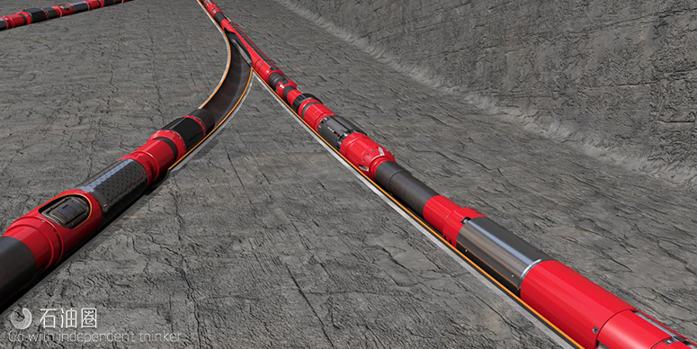
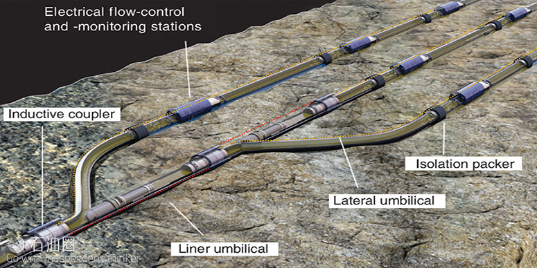
A producer and a service company have collaborated to develop a downhole system to merge multilateral technology and intelligent completions to create “smart laterals.” This approach is known as the extreme-reservoir-contact (ERC) approach to reservoir management. The complete paper discusses ERC completion technology that segments laterals into multiple compartments to provide flow rate, pressure, temperature, and water-cut measurements, together with variable choking in each compartment.
Technology-Development Program
Even the most-experienced and -diligent development teams cannot deal with an “unknown unknown,” defined here as a serious problem so deeply hidden that it eludes discovery by all laboratory prototype test methods. Therefore, full-scale tests and preliminary field trials must be conducted early as part of the development exercise. This approach was used successfully in Well Trial 1, which verified well-construction practices, and Well Trial 2, which tested prototype electrical control valves.
Executing Well Trials 1 and 2 revealed “unknown unknowns” in the pressure-gauge electronics and the assembly of the water-cut sensor. Because these were tool failures, they were relatively simple to correct. During Well Trial 3, an application failure was encountered when the drilling bottomhole assembly (BHA) tracked the liner outer diameter for several hundred feet after exiting the casing window. The resulting intersection of the electric umbilical on the outside of the 7-in. intelligent liner destroyed the downhole communications capability in the well. This problem could not have been prevented by effective planning; being an application failure, it could be discovered only in a field trial.
The application failure caused a program halt. A team was formed to redevelop lateral exit methods and drilling-sensor usage. A new project plan was made that required three additional parallel trials. Well Trial 4 was planned to prove umbilical avoidance by use of resistivity logging and revised procedures; further details are contained in the ERC Well Construction subsection of this synopsis. Well Trial 5 was a reduced-scale trial. Well Trial 6 was a full-scale installation similar to that previously attempted in Well Trial 3 and is the primary focus of this paper.
ERC Well Design
Well Trial 6 was a trilateral openhole producer for a low-permeability carbonate reservoir. Intelligent completions were installed in each of the three horizontal laterals and connected to the 7-in. wired liner by use of inductive couplers.
The well-construction method became known as “Drill-pletion” because of the repeated interweaving of drilling and completion activities. The ERC well schematic in Fig. 1 above highlights the electrical path along the 7-in. wired liner to each female inductive coupler. Each intelligent lateral connects to the 7-in. wired liner by a male inductive coupler.
The key components of an intelligent-lateral completion are the male inductive coupler, feed-through swell packers, and flow-control valves (FCVs) to deliver flow-monitoring and flow-control capability.
ERC Well Construction
The 7-in. wired liner provides multiple electrical sockets acting as connection points for the intelligent laterals and the upper completion, linked together with an external electrical umbilical. Each socket contains a female inductive coupler and an indexed casing coupling (ICC), which are paired in a prespaced-out assembly. The ICC acts as a landing profile to ensure alignment of the male and female couplers. Use of inductive couplers, umbilical, and protectors required the hole size to be increased from 8½ to 9 in. This was achieved by running a 9-in. underreamer with the drilling BHA and saved a dedicated hole-opening trip. To provide exit options for window milling on Laterals L1 and L2, the electrical umbilical was wrapped on the 7-in. liner.
The 7-in. wired liner was run to total depth (TD) without rotation. The hanger was set, and the female couplers were electrically tested. The liner was cemented in place, a cleanout trip was performed, and jetting of ICCs was conducted as necessary to ensure positive landing. The electrical test was then repeated.
The drilling of the 6⅛-in. openhole main bore used a conventional rotary-steerable system (RSS) to maximize rate of penetration. Cleanout runs were then conducted on the 6⅛-in. open hole. Torque-and-drag software was used to generate models for both the cleanout BHA and the completion string. Well Trials 1 through 3 showed good correlation between cleanout-BHA and completion-string friction factors, enabling the final cleanout trip to be used as a completion dummy run.
Cleanout runs were conducted until the required friction factor was achieved. The main-bore completion with a male inductive coupler, two FCVs, and two swell packers was made up and run to TD without rotation. Electrical tests confirmed that the inductive couplers were mated and the FCVs were functioning. The packer was hydraulically set to anchor the inductive couplers in place. The running tool was released, and electrical tests were repeated before pulling out of the hole.
The Lateral L1 whipstock was run and located axially and rotationally using the ICC as a downhole reference point. This allowed a window to be milled in an upward direction opposite to the external electrical umbilical.
For the initial lateral departure downhole, resistivity was used to eliminate the possibility of tracking the casing, as experienced in Well Trial 3. This involved closely monitoring real-time downhole resistivity-tool data to confirm wellbore separation from the liner, taking advantage of the resistivity contrast between the high formation resistivity and the low resistivity response when next to the metallic liner.
The RSS was used to ensure low dogleg severity for initial departure. Lateral L1 was drilled to TD, and the intelligent-lateral completion was successfully run and electrically tested. The Lateral L2 window was milled, the leg was drilled to TD, and the intelligent-lateral completion was successfully run and electrically tested.
The upper completion, including electrical umbilical, production packer, and male inductive coupler, was run in hole and mated to the 7-in. wired-liner inductive coupler. Total completion connectivity in all three laterals was proved by performing function tests on six FCVs. The production packer was hydraulically set, and the electrical test was repeated successfully.
Control and Monitoring
The control-and-monitoring system for an ERC well can be divided into two tiers. Tier 1 represents the acquisition of raw production data from the downhole FCVs to the surface control unit (SCU) located at the wellsite. The SCU can be regarded as a computer interface that routes control instructions to the downhole choke and receives downhole monitoring information. A remote terminal unit acts as a router between the contractor’s wellsite equipment in Tier 1 and the operator’s network in Tier 2.
Tier 2 pertains to how an ERC well is controlled and monitored. The Fundamental User is a control-room operator located at a gas/oil-separation plant that uses a real-time acquisition-and-control-system server to control the FCVs. To enable optimal decision making, the Fundamental User is provided with downhole production data, feedback data from interval-control-valve changes, and health-check information from the electronic circuits of the FCVs. These data are then stored in a plant-information database and made available to the Advanced User using a visualization tool.
Initial Learnings
New insights into ERC well-monitoring capabilities were gained from a 7-day well-cleanup program. The ability to view key production parameters directly in real time allowed immediate clarity on downhole performance.
The FCV capabilities can also be used to assist completion operations, providing more options for circulating fluids and identifying whether packers are set properly.
Typical well-cleanup operations have a criterion of flowing the well until the water cut has been reduced to a low value (for instance, 5%), indicating that the majority of the completion-brine and drilling-fluid losses have been produced out of the well. Because ERC wells have FCVs taking flow and pressure measurements directly at the reservoir, the cleanup criterion can now be changed to the productivity index. That is a much better cleanup criterion than water cut because it will determine the optimal drawdown required for filter-cake removal and identify those zones with lower-than-expected productivity index.
The next step is to place this ERC well onto long-term production. It is proposed to produce each compartment initially at a flow rate proportional to its length, the aim being to have uniform inflow into the well.
Collaboration and Program Management
Top-tier projects are often not pursued because risk cannot be understood or managed. High-level operator support goes only to these top-tier projects that meet the operator’s vision of maximizing recovery. Collaboration is the key metric to articulate value and minimize risk, enabling the operator and service company to seek out and engage top-tier projects preferentially.
The ERC project used a two-tier organizational structure that consisted of a project-management committee and a steering committee, each with members from both companies. The project-management committee created the project plan, provided monthly reports, executed day-to-day operations, and acted as gatekeeper for intercompany communications. The steering committee looked after vision, project oversight, budget planning, manpower adjustments, and problem resolution.
Conclusions
- The ERC project combined the capabilities of multilateral wells and intelligent completions. A full-scale system was developed and successfully tested in a Saudi Arabia well.
- Flow-measurement and -control capabilities were integrated into a single electrical module. The FCV was designed to measure pressure, temperature, flow, and water cut and to control flow with an infinitely variable orifice.
- A new connector system based on inductive coupling was developed. The inductive coupler can be used to branch umbilicals (ERC) or provide two-trip capabilities for extended-reach wells or to perform electrical-submersible-pump/safety-valve replacements.

 石油圈
石油圈

