Several designs for autonomous inflow-control devices (AICDs) are available. One forces inflowing fluids to enter gates, depending on inertial and viscous forces of the various fluids. Another is an autonomous valve in the shape of a free-floating disk that restricts the flow rate of low-viscosity fluids and is primarily used to choke gas and water inflow. Recently, a device with water-swellable rubber inside the nozzle has been proposed, but it is not yet commercially available. The comparative properties and abilities of these designs are the focus of this paper.
Well Model, Reservoir Simulator, and Optimizer
The well model used in this work is part of a next-generation parallel commercial reservoir simulator and features a flexible multisegmented well topology, enhanced robustness for difficult problems, and extensive well-model options. It forms part of a scalable parallel commercial reservoir simulator.
Optimizations carried out in this work used an optimizer developed to alleviate the computational cost in an optimization study where simulation-based objective functions are expensive to evaluate. When compared with several other commonly used optimizers, it was demonstrated that this optimizer outperformed others significantly.
Modeling Inflow-Control Devices (ICDs)
Various ICD designs include those with nozzle orifices, tubes, and helices. Unlike ICDs, AICDs may or may not have moving parts but they can change or modify their state in response to inflow. Design of the AICD determines the particular unwanted fluids that are delayed. There are a number of types available commercially, including a floating flapper, an oil-selector valve, an autonomous inflow-control valve, the rate-controlled-production (RCP) valve, and a fluidic diode valve. Another design recently proposed is based on inclusion of water-swellable rubber within the nozzle, but this is not yet commercially available. Both ICDs and AICDs are often deployed in a compartment whose edges are sealed with a packer, and are placed in the tubing wall between an annulus and main production stream.
These devices are modeled in advanced multisegment well models as device segments; aDepending on the field-completion strategy, there may be looped flow paths where fluid entering the well through well-to-cell connections can move in either direction along the annulus in order to find the easiest path into the main tubing.
AICD 1. Flow performance of the first AICD used in this work is based on the general flow response of a device referred to as an RCP valve. There is a free-floating disk that moves toward the inlet and chokes flow when low-viscosity fluids such as gas flow through the device. More viscous fluids produce an increase in friction loss so that pressure on the rear side of the disk decreases, the disk moves away from the inlet, and higher inflow rates occur.
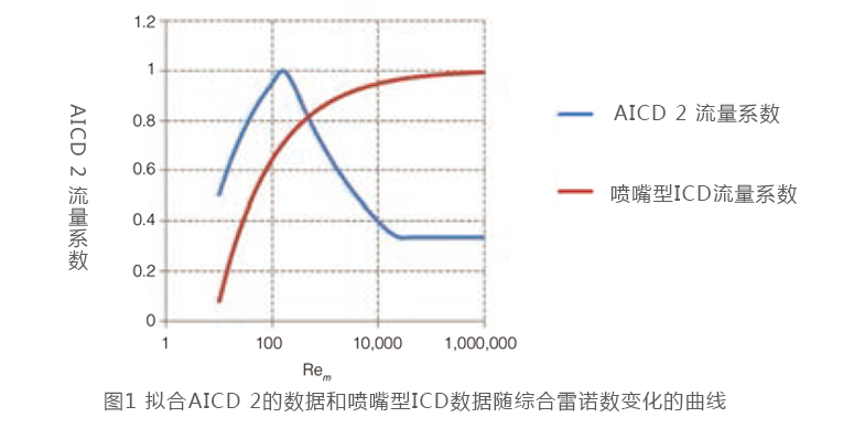
AICD 2. A fluidic diode device is designed to allow the flow of desirable fluids such as oil and restrict the flow of undesirable fluids such as water. Further improvements to this design allow more-autonomous on/off switching. Fig. 1 shows a fit of the device-discharge coefficient vs. mixture Reynold’s number. Fig. 1 also compares the discharge coefficient for this type of device with that of a standard ICD nozzle. Again, this fit is only approximate.
AICD 3. Flow performance of this device, based on a hypothetical apparatus, is designed to hold back the multiphase flow depending on water cut. It is based on a nozzle-type ICD in which a water-swelling rubber is installed directly into the nozzle. When water breakthrough occurs, the rubber swells, causing a decrease in nozzle area dependent on water cut.
To model this particular device, the multisegment well model in the simulator was extended such that internal constraints may be imposed on the flow through any segment pipe. These constraints are an upper limit on either a pipe’s molar rate or oil/water/gas volume rate, calculated at reservoir or surface conditions. If a limit is exceeded, then flow through the segment pipe is automatically choked back such that the constrained flow rate stays at the limiting value and the internal constraint is said to be active. At a later point in the simulation, an internal constraint may become inactive if the limited rate cannot be sustained; flow then drops below the limit, and automatic choking is disabled.
Field Application of AlCDs
The simulation study is based on the Ivar Aasen field (formerly Draupne field), located in the northern part of the North Sea, west of the Johan Sverdrup field. The main deposit is a midsized sand-stone oil field at a depth of approximately 2400 m in an approximately 60-m- thick oil column with a mobility ratio of water to oil of less than unity. Most of the production is limited by process capacity, first on oil capacity and then on liquid or water capacity. Field life is estimated to be 20 years.
Optimization of AICD Strengths and Design
Studies were carried out to determine optimum AICD cross-sectional areas and device calibration exponents. To determine the range of cross-sectional areas, device nozzles can be configured in groups of one, two, three, or four, with diameters ranging between 1.6, 2.5, and 4 mm. This permits a continuous range of cross-sectional areas between a single nozzle of 1.6-mm diameter to four nozzles of 4-mm diameter each.
A total of 237 AICDs are specified among the six production wells, with a single device assigned to a 12-m joint. Simulation run time for each run is approximately 60 minutes (on four cores). Clearly, the total number of optimization variables is too large for a practical optimization study. There are several ways to handle large optimization problems of this type. The “direct-continuous” approach is chosen for the current work, in which the effective cross-sectional area of each device is defined over a continuous domain. Furthermore, to reduce the number of simulation variables, groups of AICDs in each well are assigned the same set of four variables. Grouping of these variables was determined by productivity as a function of measured depth along each well. Producer 1 (with 37 devices) was divided into two groups, Producer 2 (with 47 devices) was divided into four groups, Producer 3 (with 56 devices) was divided into four groups, Producer 4 (with 16 devices) was presented as one group, Producer 5 (with 46 devices) was divided into four groups, and Producer 6 (with 37 devices) was divided into three groups. This gives a total of 18 groups among the six producers, and, significantly, only 72 control variables for optimization purposes.
Ability To Improve Oil Production and Control Water
To determine the ability of the three AICD designs to improve oil production and control water production, first, two simulations were run in which all wells were equipped with AICD Device 1 or AICD Device 2, using optimal cross-sectional areas; second, a simulation was run in which Device 3, with cross-sectional areas directly determined by water cut, was installed in all wells. Cumulative oil and water were compared for all three devices. Cumulative oil at the end of production is similar for De-vices 1 and 2 compared with the base case, although Devices 1 and 2 produce less during the middle of the cycle. Device 3 produces less oil. Cumulative water is greatly improved (reduced) with Device 3, which directly responds to water cut in each device. Device 1 also shows improved (less) water production for much of the production cycle, although by the end of production at 23 years, it has caught up to the openhole case. Device 2 produces a little more water by the end of the production period. Comparing actual production values, wells equipped with Devices 1 and 2 produced approximately 390 000 std m3 of additional oil compared with open- hole production, and those with Device 3 produced 1 932 000 std m3 less oil. Regarding cumulative water produced, wells with Device 1 produced an additional 360 000 std m3 of water, wells with Device 2 produced an additional 1 440 000 additional std m3 of water, and producers equipped with Device 3 produced 90 110 000 std m3 less water than openhole.
Discussion
Although these results are tentative because of the approximate nature of the curve fitting for Devices 1 and 2 and the hypothetical response of Device 3 to water, wells equipped with AICD 1, based on a commercially available design, controlled water better than those with Device 2 while demonstrating similar improved oil production. AICD 1 also matched optimum values of calibration parameters better than Device 2. Device 3, not commercially available, showed less oil but a dramatic decrease in water production compared with the first two devices. When properly optimized with full-field dynamic reservoir simulations, both ICDs and AICDs improve revenue and control water. This suggests that the strength of the device may be the most important parameter for this field.

 石油圈
石油圈

