Fluid sampling-while-drilling
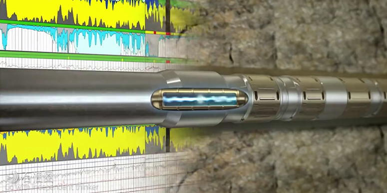
Baker Hughes introduced an enhancement of its existing sampling-while-drilling service (FASTrak HD), and an advanced fluid analysis and sampling-while-drilling service (FASTrak Prism). The new tool can collect up to 16 discrete single-phase representative fluid samples per run—a total 13.4 liters of total fluid—resulting in significant rig time reductions and cost savings. Continuous measurement and analysis of pumped fluid during sampling operations makes it possible to acquire samples with minimal contamination.
In addition to the existing optical sensors, the new advanced fluid analysis service adds spectrometry in the visible-to-near-infrared range and fluorescence measurements to distinguish between fluid types. The new spectrometry module consists of 13 optical channels, six of which are assigned to the visible range (400 to 800 nm) and seven channels to the near-infrared range (1,400 to 2,000 nm). A spectrum of the fluid pumped (oil, gas and water) can be obtained by using a series of wavelength-selective detectors, which allows improved fluid identification and a more accurate fluid analysis.
Since crude oil components exhibit strong fluorescence and the spectrum of emitted light is characteristic for specific components, a fluorescence measurement allows the content of these different components to be determined and used to distinguish between an OBM and formation oil. The fluorescence measurement has proved to be the best indicator of cleaning up from OBM-filtrate towards oil.
Schlumberger’s new fluid-sampling and analysis service (Spectrasphere) provides laboratory-quality while-drilling fluid analysis: downhole fluid composition, fluid typing, fluid fractions and gas/oil ratio. The service is suited to high-angle and extended-reach wells, where newly designed stabilizers can be placed between the modules and repositioned, depending on the well profile, to reduce the risk of sticking. The service comprises three modules: (1) a pre-test probe, (2) a fluid mapping module, and (3) a sample carrier module.
The pretest probe provides accurate measurements of formation pressure and mobility to determine the best reservoir interval to test. It can operate as a stand-alone formation-pressure-while-drilling tool, or in combination with the other two modules for fluid typing and sampling operations. The fluid-mapping module includes a pump-out module and one or two downhole fluid analyzers (DFA), each of which includes an optical spectrometer, resistivity cell, and temperature cell. The DFA uses visible and near-infrared spectrometry data to provide sample contamination estimation, fluid resistivity and temperature, fluid typing and compositional analysis, and in-situ GOR measurements.
Sampling operations can be driven at a constant rate or constant drawdown pressure. The sample carrier module can acquire up to 12 PVT-grade fluid samples in a single run. The sample containers are mounted on the outside of the driller and protected by removable shields. The service modules are available in a 6¾-in. drill collar and are temperature-and-pressure rated to 302°F and 25,000 psi, respectively.
Kick detection
The DOE National Energy Technology Laboratory (NETL) has patented, and is seeking to commercialize, a method using LWD/MWD instruments to detect kicks at the bit. This approach would leverage data from standard and cost-effective LWD technologies to provide early and low-cost kick detection. The concept is that highly sensitive LWD/MWD instruments can be refocused to detect drilling fluid in the wellbore. The method evaluates the LWD, using a suite of filters and algorithms to monitor wellbore conditions near the bit in real time. Because the physical properties (e.g., density, resistivity, and velocity) of this fluid are well characterized by the driller, detection of significant changes in these properties caused by the mixing of formation fluids could indicate that formation fluid influx (kick) has occurred downhole. This information could then be provided to the driller earlier than conventional kick-detection methods, enabling remedial action before the kick arrives at the surface.
OPENHOLE WIRELINE LOGGING
Through-the-bit logging
Schlumberger’s ThruBit has introduced two new tools to the suite of available services, a high-resolution laterolog array tool and a microelectrical imaging device. These 21/8-in. diameter tools are deployed through a 2½-in. opening in the center of a specially adapted PDC bit. The laterolog array tool (LAT) , which has the same architecture and 12-in. vertical resolution as the larger-diameter wireline LAT, can be run in borehole diameters between 3- and 16-in., while the imaging tool is designed for borehole sizes ranging in size from 5½-in. to 9¾-in. Both tools require conductive mud systems (the imaging device requires WBM), and are fully combinable with other through-bit services. They are rated to 300°F and 15,000 psi. Due to the nature of the deployment, the LAT is run without centralizers and may require eccentricity corrections, particularly in horizontal wells.
The through-bit imaging tool was designed specifically for horizontal well applications. It uses a 12-arm bowspring design that provides 0.2-in. spatial resolution and achieves 76% borehole coverage in a 6-in. borehole. Images are acquired in memory mode. The tool design and conveyance method required new and tool-specific data processing methods.
Roller and holefinder system
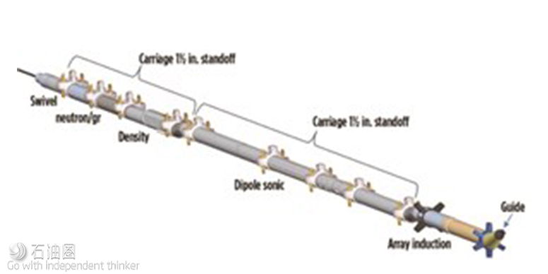
Petromac introduced a new conveyance system to assist logging in high-angle wells (up to 80°). The system comprises a newly designed holefinder and roller device that can accommodate the full suite of mandel-type logging tools, Fig. 4. The holefinder (guide) is angled and tapered to allow it to readily pass over ledges or other obstructions in an open borehole. The roller device (carriage) fits over the exterior of the logging tool housing and is secured to the logging tool at regular intervals (3 to 4 m) along the toolstring. The carriages, which use large-diameter narrow wheels and low–friction bearings to minimize drag and differential sticking, come in centered and eccentered models to optimize the logging tool measurements. In combination with a tractor device this system can be used to log horizontal wells.
Gamma-ray tool calibration.
Since 1959, the API formation maintained by the University of Houston has defined the API unit to which wireline natural gamma-ray tools are calibrated. However, the borehole at the UH calibration facility is too narrow to accommodate large collar-size LWD tools. Consequently, there have never been standards or recommended practices for characterizing LWD gamma-ray tools that do not fit into the test borehole. This has resulted in uncertainty on how to compare wireline and LWD gamma-ray measurements.
However, the university is planning to develop the real estate around the test borehole, and it will soon be unavailable for testing. Two recent papers proposed modeling-based approaches to replace the facility by varying the borehole size to match the tool OD being calibrated, and thus accommodate wireline and LWD tools.
One approach uses a combination of computer modeling and a single experimentally determined calibration point and an uncased “digital API formation” that emulates the UH formation. This method provides improved agreement between wireline and LWD logs, because they are all calibrated in the same formation and in their natural logging positions.4 This model matched the sensitivity of a wireline tool calibrated in the UH formation to within 1%; the modeled sensitivity of an LWD tool compared favorably to the measured sensitivity determined with granite blocks. The second modeling approach uses accurate nuclear and formation parameters representative of the UH facility, and tool geometry.
NGD vs. GGD porosity measurements
This article has covered the ongoing debate on the comparison of porosity derived from the new sourceless density measurement (neutron-gamma density) and porosity derived from conventional density measurements acquired using a radioactive chemical source (gamma-gamma density). A theoretical sourceless tool was designed at the University of Texas that optimized source-detector spacing for maximum accuracy. Synthetic examples demonstrate that the accuracy of the tool design for resolving formation density in clean and shalely formations, high-density formations, and gas-saturated formations is similar to the GGD density, and the measurement remains stable for porosity estimates within ±1 porosity unit.
Resistivity logging
Researchers at the Colorado School of Mines discussed the theory of a coincident-loop transient induction wireline tool. In contrast to conventional frequency-domain induction tools, this device would use the time-domain electromagnetic method。 The proposed coincident loop sounding eliminates the need for a physical separation between transmitter and receiver, as well as bucking (focusing) coils. If the correct time gates are chosen for a measurement, this method would be effective in determining formation resistivity in the presence of shoulder beds, borehole fluids, and invasion.
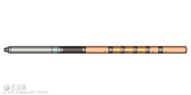
Researchers at IPGG SB RAS have tested a prototype high-resolution multi-frequency device to study resistivity anisotropy and thin-bed evaluation. This “excitation-observation” system excites an alternating electric field with both vertical and horizontal components in the surrounding formations. The signal received by the toroidal receiver coils is a function of both the vertical and horizontal conductivity of the formations surrounding the borehole. Both the summary and differential excitation modes are used to increase the spatial resolution. The prototype tool includes a telemetry module and a sensor section.
The sensor section, which is split into an insulator and a transmitter-receiver section, comprises a nonmagnetic metal stem and two toroidal transmitting coils on either side of three toroidal receiver coils, Fig. 5. The coils are placed symmetrically, with respect to the center of the tool, and the length of the probe is 1.2 m. The close spacing of the T-R coils enables the high vertical and radial resolution. Operating frequencies range from 5 to 500 kHz.

 石油圈
石油圈


