A Permanent Fiber-Optic Wellbore-Fluid-Level Monitoring System
To efficiently produce an oil rim and not the overlying gas cap or the aquifer below, it is important to be able to monitor the oil-rim position. In highly fractured carbonate reservoirs, such as those in the Sultanate of Oman, the oil rim may be thin and highly dynamic. Therefore, monitoring is particularly important in allowing an intelligent well-production methodology wherein numerous wells are drilled across the reservoir and the operator selects production rates and timing and whether to inject water and gas below and above the reservoir to control the position of the oil rim.
Background
The conventional method of monitoring oil-rim movement is by periodically running wireline gradiomagnetic surveys in which a suite of measurement tools is lowered into the observation well to measure the levels and compositions of the fluids in the wellbore. In highly permeable or highly fractured reservoirs, there is good communication between fluids within the formation and within a perforated observation well, so fluid levels in the wellbore give the operator enough information about the oil rim within the reservoir to adopt an intelligent well-production methodology.
While the use of gradiometric surveys for production optimization is helpful, it does pose certain disadvantages. Each survey requires a well intervention with a wireline unit and crew at the wellsite during the entire process: well opening, pressure containment during the survey, and closing. This makes the process relatively expensive and carries health, safety, and environment (HSE)-related risks while the well is open. As a result, gradiomagnetic surveys are generally commissioned at a low frequency, perhaps only one or two measurements per year within key observation wells.
Knowledge gained from recent work has highlighted that such a low frequency of oil-rim measurement misses the identification of the highly dynamic changes in the oil rim that occur as a result of production operations and leads to lost opportunities to improve production management significantly. Instances have been recorded in which the lack of timely information from gradiomagnetic surveys has led to loss of control of the oil rim and significant production deferment.
Development and Trial
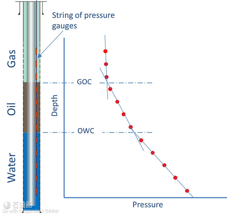
In the early 2000s, Shell’s in-well technology team in Rijswijk recognized the potential to provide an array of permanently deployed pressure gauges through the fluids within the wellbore to measure the density of the media between adjacent gauges, from which one could accurately derive the interfaces between the media of different densities. As shown in Fig. 1, this delivers the same results as the periodic gradiomagnetic surveys (i.e., the location and thickness of the oil rim in the wellbore sandwiched between the upper gas layer and lower water aquifer).
Pressure transducers have been used by the industry for several decades. However, these electronic gauges are not optimal for use in the described application because of their relatively short service life at the elevated temperatures found in wellbores, and the logistical difficulties and high cost associated with deploying a string of multiple electronic gauges in a single well. Instead, the emerging use of optical-fiber Bragg gratings (FBGs) for pressure-metrology applications was considered. FBG technology brought with it the key capabilities required to deliver the permanent distributed pressure and temperature sensing (DPTS) needed for fluid-contact monitoring—the gauges required no downhole electronics and thus offered long service at elevated downhole temperatures; the technology offered the potential for the long-term stability required to detect the subtle pressure changes resulting from small fluid-level changes; and dozens of FBG pressure gauges could be deployed in series on one optical cable connected to a single surface acquisition unit (SAU).
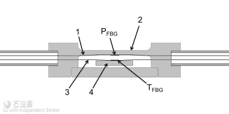
In 2003, Shell began working with the UK’s Smart Fibres on the development of a diaphragm pressure gauge able to provide a permanent downhole DPTS function. The resulting transducer (Fig. 2) converted changes in the hydrostatic pressure of its surroundings into the deformation of a pressure-sensitive diaphragm, and then into the strain within an optical fiber attached to the diaphragm. This strain can then be measured by the SAU by means of the wavelength reflected from an FBG using the so-called Bragg equation.
In a collaborative development project, Smart Fibres focused on the design of the downhole gauge and surface interrogator for long-term stable measurement, while Shell focused on the deployment methods and integration of the measured data into their operating units’ information-technology infrastructures to deliver real-time oil-rim-position data to the desk. A first trial deployment was made in 2010 in a carbonate reservoir in which nine downhole gauges were deployed on a 3½-in. tubing string and then connected by a downhole optical cable to a solar-powered SAU. Distributed pressure and temperature data were transmitted from the SAU by a remote telemetry unit and then processed into fluid-contact levels using a bespoke algorithm.
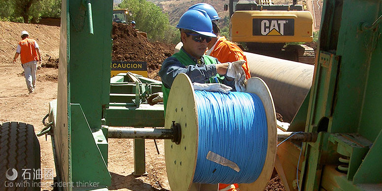
This first deployment was an important milestone on the road to developing a commercial DPTS system. Two further trial deployments, in 2012 and 2014, were performed to demonstrate that the solution could be replicated and to validate the system improvements. Also, a new deployment methodology was developed and demonstrated in two commercial deployments wherein the array of downhole pressure/temperature gauges is preassembled and factory acceptance tested before shipping to the field. This spooled deployment methodology brings reduced field-installation time, thus lowering deployment cost and HSE risk.
Results
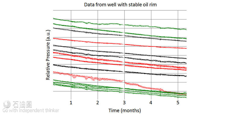
The three trial deployments progressively provided more-accurate data and greater system reliability. In particular, the stability of the pressure measurements from the downhole optical gauges—critical to avoid a false indication of fluid contact movement—was very high. Fig. 3 shows data from 14 gauges in a relatively stable well where the gauges faithfully track each other, apart from one seen to be transitioning from the oil phase to the gas phase and thus reporting reducing pressure. In order to give an indication of scale, the differential pressures between gauges in the gas phase are approximately 1 kPa (0.15 psi), which demonstrates the stability of the individual gauge measurements.
System Value
Using a suite of visualization tools, the operator’s engineers were able to view real-time and historical pressure, temperature, and fluid-level data which were used to influence their production-optimization program. Fig. 3 shows an example dataset where the oil layer in the observation well is seen to disappear twice in a 6-month period. Armed with new real-time knowledge of this dynamic behavior, engineers can now take preventive action to maintain the oil-rim thickness and position.
Providing a quantitative statement of the system value is not possible because of the confidential nature of production rates and other operational statistics. However, the ways in which the system has been seen to provide value can be summarized as follows.
Improved reservoir understanding. Moving from an inconclusive periodic observation well gradiomagnetic survey policy to real-time monitoring is considered a requirement, and significant production improvement estimates have been calculated without considering additional gains related to gas injection compressor constraints and uptime.
Reduction of production deferment. Use of real-time monitoring prevents the repeat of previous situations in which gradiomagnetic surveys missed the thinning and the lowering of the oil rim, resulting in a decrease in the overall field production.
Operational expenditure reduction. Long-term cost reductions can be seen when comparing the cost of a single DPTS system deployment with that of repeated gradiomagnetic surveys.
HSE risk reduction. A DPTS system requires only one well intervention during the life of the well completion, compared with repeated gradiomagnetic surveys that require continuous intervention and exposure of field crews to HSE risks.
System-expansion capability. The fiber used in the DPTS system could also be used for distributed acoustic sensing, vertical seismic profiling, or distributed temperature sensing, thereby enabling the simple addition of other monitoring systems.
Conclusions
In a collaborative project, the possibility of measuring fluid levels in a wellbore by use of distributed optical pressure gauges was conceived, prototyped, field-trialed, and further developed to a point of widespread commercialization. The system provides real-time data to the desk of the operators’ reservoir engineers, informing their production-optimization decisions and delivering significant value.
The performance of the final trial deployment led to the determination that the system was sufficiently mature to pass its final technology readiness level, thereby signaling to its operating units that the DPTS solution is commercially available. The volume commercial supply of multiple well systems is now under way.

 石油圈
石油圈


