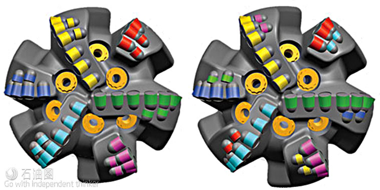
Successful drilling operations in challenging formations rely on drill bits that can provide higher-than-average rate of penetration (ROP) and reliability when drilling long intervals. There are many different types of technologies that can help achieve this performance goal, all with varying results. Yet, one of the major drivers of drill bit performance gains in recent years has been development of new, more energy-efficient layout methodologies, created for targeted applications.
A common practice when drilling an interval through a soft formation section, and into a hard and abrasive formation section, is to use at least two polycrystalline diamond compact (PDC) bits—a bit with an aggressive cutting structure (with less diamond volume) to drill the soft section and another, less-aggressive bit (with more diamond volume) to drill the hard and abrasive formation. This practice significantly increases operational costs that are related to tripping a bit out of the borehole and putting another bit back on bottom. These costs are increased further, if premature bit damage occurs, requiring unplanned trips and additional bits. Efforts have been made to replace the use of two PDC bits, with only one bit, by adding secondary rows of cutters—also called backup cutters—to the blades to share cutting responsibility when the primary cutters experience heavy wear. This results in the drilling of longer intervals, though ROP is sacrificed.
A PDC bit with backup cutters usually has two layers of cutting elements. The first layer is formed by the primary cutters, and the second layer is formed by the backup cutters. The backup cutters act as a secondary cutting structure that helps cut the formation after the primary cutter sustains significant wear. However, the depth-of-cut (DOC) of the backup cutters should be limited, when the primary cutting structure is still in good condition. The DOC is defined as the distance, a drill bit or a cutter advances into the rock during one revolution of the drill bit. The secondary layer traditionally is designed to ensure, the backup cutters do not unnecessarily cut into the formation while drilling ahead in the soft formation section. Meeting these design objectives without compromising ROP is challenging, and is a continuous goal of the drill bit industry.
A NEW CUTTING STRUCTURE METHOD
Halliburton Drill Bits and Services (HDBS) has introduced a new cutting structure design method to optimize the backup cutter layout, which will extend bit life without sacrificing ROP or increasing costs in certain applications. The method solves these challenges:
1.Helping ensure backup cutters do not unnecessarily cut formation when the primary cutters experience little to no wear, and when the DOC of the bit does not exceed the necessary value. This aspect is enabled by designing the backup cutters to have a minimal critical depth-of-cut (CDOC) that is greater than the DOC of the primary cutters. The CDOC is defined as the DOC, when a specific element or elements begin to engage rock, due to the underexposure value based on the bottomhole pattern.
2.Helping ensure backup cutters act as primary cutters when the standard primary cutters’ wear depth is equal to, or greater than, the underexposure of the backup cutters. This aspect is enabled by designing each backup cutter to rotate behind its primary cutter by approximately 180° or greater. The underexposure of each backup cutter, relative to its primary cutter, is carefully calculated, based on the primary cutter’s expected wear, and on the drilling slope derived from the expected drilling parameters and rock strength.
To help ensure that the backup cutters function as designed, a cutter-wear model, as well as newly-developed software, was integrated into the bit design tool to calculate the backup cutters’ radial locations and exposure levels. This software helps demonstrate how both primary and secondary cutting layers engage the formations at different operating conditions and rock strengths. The software also helps demonstrate where efficiency gains can be made without overloading parts of the cutting structure. In summary, the location of a backup cutter should meet the following conditions:
1.Track-set or in the same radial position on the bit profile as its primary cutter.
2.Angular location, relative to its primary cutter, greater than or equal to 180°.
3.Underexposure greater than, or equal, to the expected wear depth of its primary cutter.
4.CDOC greater than, or equal to zero, which is the expected DOC when its primary cutter experiences no wear.
When a primary cutter experiences little to no wear, the underexposure of its backup cutter should be designed so that the backup cutter cannot engage the formation under normal drilling conditions. In other words, the CDOC of the backup cutter should be greater than the expected DOC. An ideal condition would be that each backup cutter has the same CDOC, so that when the actual DOC is greater than the CDOC, all of the backup cutters can engage the formation simultaneously. Therefore, backup cutters act as DOC controllers when the primary cutters experience no wear. This CDOC design ensures maximum drilling efficiency before the onset of abrasive wear.
When a primary cutter experiences a wear depth that equals a value close to that of the underexposure of its backup cutter, the backup cutter is expected to act as a primary cutting element. This is accomplished by designing the rotational location of each backup cutter behind its primary cutter by approximately 180° or greater. The underexposure of each backup cutter, relative to its primary cutter, is calculated carefully, based on the primary cutter’s wear and on the drilling slope derived from the expected drilling parameters and rock strength.
PDC cutters are abrasion-resistant but still susceptible to the same principles of wear as other materials, primarily friction. As a cutter begins to wear, more area is exposed to the rock. This increased area reduces the cutting efficiency of the PDC element. A large portion of the energy is lost as friction from the increased contact area, instead of being used to fail the rock. Increased friction is translated into heat, which in turn accelerates the wear, culminating in a vicious cycle of rapidly increasing wear.
The new cutter layout method being deployed breaks this cycle by allowing a sharp cutter to take over rock failing duties before the rapid acceleration of wear. The key to success is proper placement, as engaging cutters too early, too late, or at the wrong location, can yield zero benefit. Proper understanding of the application and utilization of the correct design tools and bit wear progressions has allowed this design methodology to be successful. Field applications of the new bits designed with this method have extended bit life significantly, without sacrificing the ROP.
FIELD RESULTS
A new bit design utilizing this cutting structure layout methodology was applied during the drilling of a 6 3/4-in. lateral section in a tight, abrasive sandstone known as Mulichinco in the Neuquén basin of Argentina. Typically, several PDC bits are necessary to drill through this 1,100-m section. The primary challenge is the heavy wear sustained by the nose cutters and shoulder cutters, which causes a rapid decrease in ROP with the same drilling parameters as the cutting structure declines. Impact arrestors were used as DOC elements toward the center of the bit, to help prevent over-engagement of inner or cone cutters and provide more material for cutter retention, due to the abrasive nature of the formation being drilled.
Because of the decrease in ROP that resulted from wear on the cutters, it was determined that keeping the primary cutting structure as sharp as possible was paramount in maintaining ROP and increasing bit life. In the new design, backup cutters were added on the nose and shoulder zones at a specific CDOC, to help prevent early cutter wear and damage.
The underexposure of all backup cutters was also set at a specific CDOC to ensure that all backup cutters act as primary cutters when primary cutters experience wear. All backup cutters were designed and placed to rotate four blades behind primary cutters. This arrangement helps ensure that all backup cutters are approximately 250° behind the corresponding primary cutters, so that the backup cutters become the new primary cutters, and so that the original primary cutters become secondary cutters when the original primary cutters experience heavy wear.
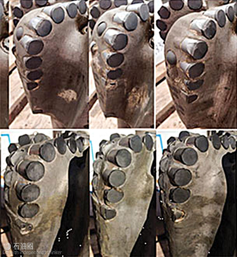
During drilling, both the new backup and primary cutters experienced wear, but the wear depth was much smaller than the cutters on previous designs, even though the new bit drilled almost double the distance of previous designs in the same formation. This achieved the goal of the new bit design.
In a second application in Rahaya field in West Kuwait, a 9 1/4-in. vertical section required drilling in the Zubair abrasive sandstone (approximately 335 m), Ratawi shale and limestone formations, with a total interval length of 891 m (from 2,898 m to 3,885 m). Historically, at least two PDC drill bits were necessary to drill this challenging interval—a highly durable bit to drill through the Zubair sandstone and another, more aggressive bit to drill the Ratawi shale and limestone.
After a detailed study of the bit performances from offset wells, it was determined that the first bit’s rate of cutter wear needed to be reduced to drill through the Zubair sandstone, and to ensure that it could drill through the Ratawi shale at a high ROP. The cutting structure of the second bit, which drilled through the Ratawi shale and limestone, was designed properly, meeting performance expectations and sustaining an appropriate dull condition. To reduce operational drilling costs, it was proposed that one bit might be able to drill this section with a strategic layout of the backup cutters in a reduced total time.
The study revealed that the CDOC for all of the backup cutters should be around 1.14 mm per revolution (mm/rev), at an RPM of 120. This means that backup cutters should not engage the formation when the bit penetration rate is less than or equal to 8 m/hr. It also was determined that backup cutters in the nose and shoulder zones should act as primary cutting elements, when the primary cutters experience a wear depth of approximately 0.58 mm to 0.66 mm.
Using the same principle described in the preceding sections, a new bit was designed. For this seven-blade bit, all backup cutters are rotationally located four blades behind the associated primary cutters, respectively. For example, the backup cutters on Blade 4 are associated with the primary cutters on Blade 1, approximately 210° behind the primary cutters. Almost all backup cutters have the same CDOC of 1.14 mm/rev. When the actual DOC is more than 1.14 mm/rev, all backup cutters can engage the formation simultaneously. Therefore, backup cutters act as DOC controllers, when the primary cutters experience no wear.
The new design drilled the entire 891-m distance, which is the longest footage drilled in Rahaya field in West Kuwait. The bit drilled through the Zubair, Ratawi and the entire Minagish formations, with an average ROP of 6.05 m/hr faster than most of the offset bits. The bit’s cutting structure was in good condition with a 1-1-WT-A-X-I-NO-CP/TD dull grade.
CONCLUSION
There is typically a trade-off between drilling efficiency and rate of penetration, and between durability and wear resistance, in abrasive applications. More aggressive bits initially drill fast, but wear quickly and lose ROP as a result. Less aggressive bits with backup cutters put more diamond on bottom, giving them additional life but also resulting in less ROP. The team’s new modeling techniques and understanding of cutter rock interaction enabled HDBS to take advantage of engagement area splits at specific drilling slopes and wear rates. This technique ultimately allows a bit to be designed that increases drilling life with minimal impact on ROP.

 石油圈
石油圈


