One of the first uses of inflatable packers was while cementing during the well construction phase. The inflatable element was mounted on casing and used as a base for secondary or off-bottom cement jobs. This is still a common use of inflatable tools. During a well’s producing life, inflatable tools are often used while servicing a well, when a downhole restriction is present that excludes the use of a mechanical bridge plug or packer. For example, inflatable elements can be passed through production tubing on wireline to perform a plug-back, or they can be used with coiled tubing to perform a thru-tubing squeeze job. The thru-tubing operation is preferable; otherwise, operators have to kill the well to perform an intervention. Inflatable tools are also well-suited for use in open-hole barefoot completions, when well testing or water shutoff is required. For offshore wells, where section milling is often needed during P&A operations, inflatable tools are ideal.
WHAT IS AN INFLATABLE TOOL?
The critical component of any inflatable tool is the inflation element. The basic components of an inflation element are the inner bladder, the support structure, and the elastomer cover. The inner bladder expands and contains the inflation fluid. Outside of the inner bladder is the reinforcement or support structure, which can be made of cable, stainless steel slats, or a combination of the two.
Outside the support structure is the elastomer cover, which creates the hydraulic seal. The choice of which of the two reinforcement designs to use – a weave support made of cable or a stainless steel slat support – depends on the application. The inflation element with the weave reinforcement is best-suited for open-hole applications, where its exceptional multi-set capability and easy conformance to irregular borehole shapes offer a distinct advantage.
For cased-hole applications, the stainless steel slat reinforcement is preferred, because a portion of the fortification can be exposed to achieve anchoring. The element is anchored through the friction force generated in the contact area of the exposed slats, once the internal inflation pressure is applied.
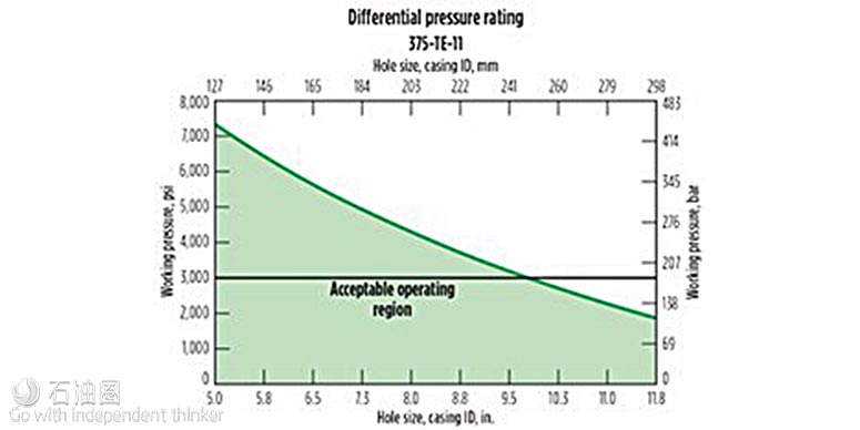
The inflation element’s expansion ratio is determined by the inflation element type and the well conditions. The weave elements have an expansion ratio of 2:1, which means a 4?-in. OD element can inflate to 8?-in. The slat element can achieve an expansion ratio of 3:1, so that a 21/8-in. OD element can inflate to 63/8-in. The differential pressure rating of an inflation element is dependent on two main factors: the expansion ratio and the temperature at the setting depth. As expansion ratio and temperature increase, the differential pressure rating decreases.
The choice among the different sizes of inflation elements depends on the type of tool. For service tools, inflation elements start at 1.69 in. and go up to 15-in. For casing annulus packers (packers manufactured onto casing), the sizes start at 23/8-in. and go up to 30-in. The type of application determines the type of tool that the inflation element is placed on.
The basic service tool components are a control sub equipped with an inflation mechanism, a packer mandrel, the inflation element, and a release mechanism to unset the packer if retrieval is required. The inflation mechanism is designed with different options, depending on the deployment method and application. For example, wireline deployment versus drill pipe or coiled tubing, application requirements for a single set versus multiple sets, and vertical or deviated (including horizontal) well geometry.
For most single-set bridge plug applications, a ball is used to initiate inflation by landing on a ball seat inside the control sub. Once the ball is on seat, fluid is diverted into the inflation element. When the designed inflation pressure for an application is reached, the inflation mechanism will lock in the inflation pressure. To release from the set bridge plug, a hydraulic or mechanical release mechanism can be used, depending on the deployment method.
For applications that require pumping through the tool, a packer configuration is used. The basic components are the same as in the bridge plug, but there are more options available for the inflation mechanism. A ball can be dropped in instances where the packer is required to be set only once, such as for a cement squeeze job. For multi-set operations, an auto piston device is available, where no ball is required. Operators simply apply pressure to the tubing, which causes the packer to inflate. Once the inflation element is set, slacking off weight on the device will lock in the pressure and allow flow to resume through the tool. This type of configuration is common when treating with acids or solvents, with a fluid control device run above the packer.
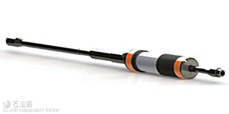
A straddle is created by adding a lower packer, Fig. 3. Two packers can be run together, separated by tubing with perforated pup joints, to allow selective isolation pumping into a formation or flow testing a formation. The packer spacing can be as close as 10 ft apart, or as far as hundreds of feet apart, if required for the application. Single-set options in straddles also can be configured, if a scab liner is required to shut off water flow.
Inflatable service tools can be deployed on drill pipe, tubing, coiled tubing, or wireline/slickline. The tool configuration chosen is based on the conveyance method. For applications where deployment is on wireline or slickline, a battery-operated inflation tool is run to inflate and set the plug or packer. This method is attractive due to its low cost, compared with using a rig or a coiled tubing unit. For single-well offshore platforms, running on a slick line may be the only option, because of limited deck space.

 石油圈
石油圈
,套管井应用采用不锈钢条设计加固(右).jpg)


