通过对比分析巴肯中部连续油藏区域内的油井完井方式,本文对该区域现生产中所采用的主要完井技术进行了评价,并对其完井设计、完井方法及压裂操作进行了讨论。通过与其他完井方式对比,本文重点评估了多孔压裂滑套系统(MEFSS)完井技术的可行性和生产效率。
引言
目前巴肯中部油藏最常用的三种完井方式为柱塞射孔(P&P)、单孔压裂滑套系统(SEFSSs)和多孔压裂滑套系统(MEFSSs)。石油圈原创www.oilsns.com
传统的P&P技术属于直井完井技术,后被改良,应用于水平井筒完井中。为了适应水平井开发并提高其抽汲能力,出现了复合压裂封堵技术。固井,作为P&P方法完井中井筒的传统封隔方法,却很难应用于水平井。而为了更好地实现分段压裂,现场产生了对无干扰完井系统的需求。因此,作为能够克服水平井筒完井中诸多难题的单孔压裂滑套(SEFSS)技术,在现场开始得到发展和应用。
SEFSS完井技术选用特定尺寸的球体,从井口投入,打开预先安装在完井尾管柱处的滑套。由于压裂施工采用从趾端至跟端循序泵压的方式,所以这些投球还可以提供阶段性的下游封隔。压裂滑套系统可以与裸眼环形封隔器一起使用,或者,也可以在适当位置直接固定。
在巴肯油田,一般需要磨铣掉球座,SEFSS系统并不需要通过磨铣来保证目标储层的正常生产。压裂滑套系统技术还可以避免水和化学剂的使用。与P&P不同,该技术并不需要将封隔球泵至后冲洗深度处。由于球可以直接在空气中被投置,因此在每一次压裂施工中都可以节约数百桶的水。
在应用压裂滑套技术时,许多工具都必须作为完井尾管管柱的一部分下到一定深度。与常规的下尾管操作相比,这增加了钻井后下完井套管的复杂程度。
虽然上述安装难题可以通过改进安装方法和步骤来克服,但压裂滑套系统通常还会限制可达到的压裂级数。这是由于系统中所使用的球及球座的尺寸是逐级增大的,因此会受到完井管柱尺寸的限制。同时,这些不同尺寸球和球座的使用,特别是靠近完井段趾端尺寸较小的球座,会影响分段压裂可采用的泵速。
研究背景
美国北达科他州巴肯中部油藏的油井在钻井时,根据所处盆地位置的地质特点,通常先垂直钻进7000~10,000英尺(2133.6m~3048m)至造斜点,随后通过长约600~1,200英(182.88m~365.76m),角度约为90°的造斜段,钻进到达真垂深(TVD)范围在7500英尺(2286m)至大于11,000英尺(3352.8m)之间的水平井段起点处。之后,钻进长约至10,000英尺(3048m),直径约为57/8至61/8英寸的水平井眼段。
钻井完成后,总井深通常大于20,000英尺(6096m)。下7英寸套管柱,覆盖至整个造斜井筒段并固井。下41/2英寸尾管柱至总测量深度处,并悬挂在7英寸的套管柱中。随后,采用三种完井方式(P&P, SEFSS和MEFSS)中的任意一种,建立井筒与储层的流动通道,以便对水平段井筒30处,甚至更多处的目标层段进行压裂。
本文选择四口互为补偿井的油井作为一个研究样本。该四口油井的完井方式涵盖了巴肯中部常见的三种完井技术,并具有相似的油藏性质和井身结构设计,有利于进行合理的比较。
通过对数月期间公开记录的收集和记录,可以得到油井的产量数据。根据已发表的油井参数,对产量水平进行归一化处理,并绘制相应图件以便分析。
本文的研究目的是通过分析确定,对于这一组补偿井样本,是否存在一种完井方式在提高油井产量上表现优于其他完井方式。石油圈原创www.oilsns.com
完井方式
如前所述,巴肯油藏主要采用三种常见的完井技术,包括P&P,SEPFFs和MEFSSs。前两种方式已经在文章中进行了阐述。
MEFSS
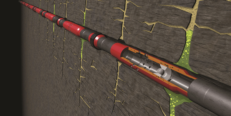
多孔多级压裂滑套系统(MEFSS)也是采用投球式开关,但一个投球即可以打开目的压裂段的多个压裂滑套。压裂滑套和封隔器与完井尾管柱安装在一起,并可以提供多个储层流动通道。
在该系统中,仍然将球从地面投入。球会落至位于压裂滑套内的坐封球座。然而,一个球将会穿过并打开多级滑套,直到落至位于目标段最后一级压裂滑套上的固定球座,并将其封堵。此时管柱内压力增大,从而打开最后一级目标压裂滑套。这时投入的球会将目标压裂滑套与上级压裂段分隔开来。这将改变压裂流体的流向,使其转而从位于目标段的多级滑套的出口孔处流出。
通常,可以根据需求来设计出口孔以平衡流出流量。随后对目标层进行压裂,并投入另一个压裂球打开上一组的MEFFS压裂滑套。重复上述过程直到完成整个目标层的压裂施工。
投入的球可以通过反排至地面进行回收,或者在井筒液中降解。
补偿井产量分析
为了给后期的分析比较提供可靠的数据,研究中对补偿井样本的生产情况进行了长达数月的监控。
文中所示的图表示了从公共数据资源中所获得的每口样本井的产量。样本中的每口井都设计有一小段位于巴肯中部储层的横向分支井,并都采用裸眼封隔器来隔离各压裂段。

图1所示为采用三种不同完井技术的四口补偿井分别在3个月和6个月时的产量数据。
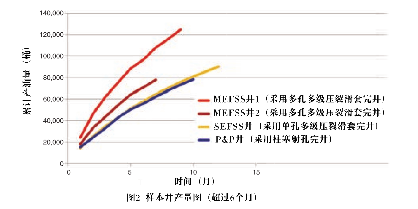
随后对四口井的产量水平进行持续监测,并绘制其结果,以便对其所用完井技术做出进一步的分析。所有井的监测时间至少为6个月,对于其中部分井,可以得到更长时间的产量结果。

图2中,累计产量曲线的颜色与其数据来源井的图例颜色相对应。石油圈原创www.oilsns.com
值得注意的是,为了得到最佳的比对分析结果,图中所示的产量结果都经过了基于油井参数的归一化处理。从所公布的产量水平来看,采用P&P完井和SEFSS完井方式的油井,其短期和长期的表现都十分相似。而采用MEFSS完井方式的两口井,无论是初始阶段还是从长期来看,则都有着更高的产量水平。
This paper evaluates dominant and currently applied completion methods by comparing wells in the Middle Bakken continuous resource play that have used all identified systems. The authors discuss these completion designs and methods and fracturing operations that are often executed. Assessment of viability and production efficiency of multiple-entry- point fracturing-sleeve-system (MEFSS) completions as compared with other completion methods is the primary focus of the complete paper.
Introduction
The three most common completion techniques in the Middle Bakken are plug and perforation (P&P), single- entry-point fracturing-sleeve systems (SEFSSs), and MEFSSs. Traditional P&P techniques were developed initially for vertical-well applications and then adapted to horizontal wellbores. As a result, composite-fracturing-plug de- sign had to evolve for horizontal-well deployment and pumpdown capabili- ties. Cementing, typically the isolation method for P&P-completed wellbores, is also difficult in horizontal wellbores. Because of the need for an interven- tionless completion system to facili- tate compartmentalized stimulation de- signs, development and use of SEFSS technologies to overcome many of these challenges came into accepted practice.
SEFSS technologies use specifical- ly sized balls that are dropped from surface to actuate sleeves that are pre- installed with the completion liner string. These actuation balls also pro- vide progressive downstream isolation as the treatment is pumped sequentially from toe to heel. Fracturing-sleeve sys- tems can be used in conjunction with openhole annular isolation packers or cemented in place. These systems do not require millout to ensure that a tar- get zone can produce, although the ball seats are typically milled in the Bakken system. Fracturing-sleeve technologies also help eliminate the use of water and chemicals because the isolation balls do not have to be pumped to depth post- flush as in a P&P technique. Because the actuation balls can be launched and landed on the fly, hundreds of barrels of water are typically saved on each indi- vidual treatment.
With fracturing-sleeve technology, many tools must be deployed to depth as part of the completion liner string. This increases the complexity of run- ning the completion casing after the wellbore has been drilled when com- pared with a conventional liner-running operation. While steps can be taken to overcome these installation challenges, fracturing-sleeve systems are often lim- ited in the number of fracturing stages that can be targeted because of the use of actuation balls and ball seats of grad- uated size against the completion tu- bular geometry. The use of graduated balls and ball seats can also have an effect on the rate at which fracturing stages can be pumped, especially for smaller-sized ball seats toward the toe of the completion.
Background
North Dakota Middle Bakken well- bores are typically drilled to a vertical-depth kickoff point of 7,000 to 10,000 ft, depending on basin geo- graphy; then, a curve is built to approxi- mately 90° in 600 to 1,200 ft, yielding a horizontal-wellbore start at a range of 7,500-ft to greater than 11,000-ft true vertical depth. From there, a 5?- to 6?-in. horizontal-wellbore section is drilled up to 10,000 ft, thus cre- ating a total well depth often greater than 20,000 ft. A 7-in.-casing string is run and cemented in place through the curve section of the wellbore. A 4?-in. completion liner string is run to total measured depth and hung off in the 7-in. main-bore casing string. One of three completion techniques is then used to create access to the formation and en- able the fracturing of 30 or more target zones along the horizontal section of the wellbore.
A sample of four wells was then se- lected that were offset to each other, as well as employing each of the com- mon Middle Bakken completion tech- niques. The offset-well sample had simi- lar characteristics and wellbore designs so that viable comparisons could be made. Production results from the wells were then gathered and recorded from public records over the course of sev- eral months. The production levels were then normalized on the basis of report- ed well parameters and graphed so that analysis could be performed. The goal was to determine for the offset-sample group whether one completion meth- od increased wellbore productivity over the others.
Completion Methods
As mentioned previously, wells in the Bakken system primarily apply three common completion techniques. The techniques include the P&P process, SEFSSs, and MEFSSs. The first two of these systems are detailed in the com- plete paper.
MEFSS. An MEFSS is also ball-actuated; however, a single ball will open mul- tiple fracturing sleeves in the target fracturing stage. The fracturing sleeves and isolation packers are installed with the completion liner string and pro- vide multiple entry points to the for- mation. Once again, an actuation ball is dropped from the surface. The ball will land on the ball seats inside each frac- turing sleeve; however, the actuation ball will pass through multiple sleeves, actuating them, until it will then seat and seal on a fixed ball seat in the last fracturing sleeve in the target stage. In- creased pressure will then open the last target fracturing sleeve. The actuation ball then isolates the target fracturing sleeve from previous fracturing stages and diverts fluid flow out the exit ports in the multiple sleeves in that target stage. Often, these exit ports can also be customized to balance outflow. The target zone is then stimulated, and an- other fracturing ball is dropped to ac- tuate the next set of fracturing sleeves in the MEFSS. The process is repeated until all target zones are stimulated. The actuation balls can then either flow back to surface or degrade in the well- bore fluid.
Offset-Well Production Results
Production results from the offset-well sample were monitored over a period of several months to provide the best possi- ble data set for comparison. The graphs in the complete paper illustrate the pro- duction from each of the sample wells obtained from public data sources. Each of the wells in the sample had a short lat- eral design drilled through the Middle Bakken layer of the formation. The wells in the sample used openhole packers as the annular isolation method between fracturing stages. Fig. 1 illustrates the 3- and 6-month production results from the four offset wells that used the three different completion techniques.
Production levels from the four off- set wellbores were then monitored con- tinually and graphed against each other to enable further analysis of the com- pletion techniques used. While all wells could be monitored for a period of at least 6 months, production results for some of the wells could be obtained for a longer period of time. The results depicted in Fig. 2 feature colors cor- responding to the well from which the production results were obtained.
It is important to note that the pro- duction results were normalized for sev- eral well parameters so that the best comparison could be made and analy- sis could be conducted. On the basis of the reported production levels, it ap- pears that the P&P and SEFSS wells per- formed very similarly in both the near and the long term. However, both of the wells that used the MEFSS completion technique had higher production levels, both initially and long term.
未经允许,不得转载本站任何文章:

 石油圈
石油圈


