Solving The Blind Spot Problem With Reentry CT Drilling
While the main drilling attention over recent years has been about new unconventional and deepwater wells, nearly 70% of the world’s hydrocarbon production comes from declining fields. There is a compelling economic case that extracting more from known reservoirs is a better idea than the cost and risks of a new project. In practice, working over mature fields involves various EOR techniques and reentering wells to drill horizontal laterals from a window cut in the existing wellbore. An established if not yet widely adopted technique to do this is to use coiled tubing (CT) drilling to drill in underbalanced conditions.
Declining well challenge
An efficient operation is an essential requirement for working over wells that might have a limited production capacity but at the same time still have significant unrecovered reserves. It is not realistic to expect a multiyear payback time, especially with a low and uncertain oil price environment. Drilling in the right direction is a fundamental requirement of directional drilling, and drilling in the wrong direction, even if the error is only small, is one of the easiest ways to reduce efficiency. This is surprisingly easy to do because of the distorting effect of steel casing on the magnetic sensors of a CT drilling bottomhole assembly (BHA), which creates a blind spot when first exiting the window. This effect might extend as far as 6 m (20 ft) from the vertical casing. While this is a problem for all casing exits, the problem is worse for CT drilling operations. There often is limited vertical depth between the window and the target formation, so high build rates are required, and this leaves little room for error.
Blind spot
Most MWD tools use magnetic sensors to help the driller steer the drilling BHA on the desired azimuth. This is perfectly acceptable in openhole conditions but not in or near steel casing, where the magnetism of the steel swamps the earth’s magnetic field and induces large and unpredictable errors in the azimuth reading, meaning the driller is effectively drilling blind.
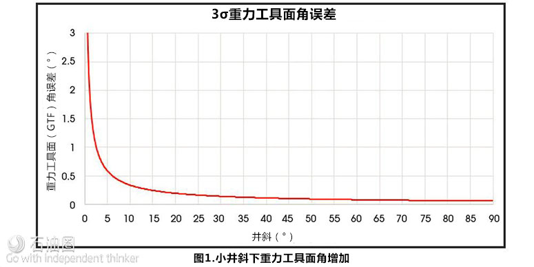
Two measurements are required to drill accurately out of a casing window: toolface and azimuth. In a vertical well both of these measurements are derived from magnetic sensors, so they cannot be relied on. Sometimes, if there is a sufficient inclination (usually taken to be more than 5 degrees) and the trajectory of the well already is accurately known, it is possible to kick off using only the inclinometer of the directional sensor. However, just as it is not possible to use a plumb-line to indicate any direction other than down, an MWD steering tool cannot give an accurate toolface when inclination approaches zero. Below 5 degrees of inclination the toolface error increases dramatically (Figure 1). The trouble is that the vast majority of reentry drilling opportunities for CT drilling are from vertical wells.
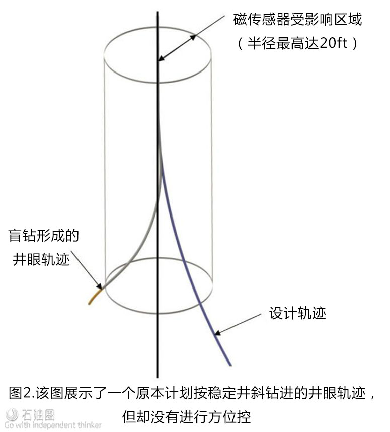
Using gravity toolface at low inclinations creates uncertainty when setting the whipstock as well as when drilling the initial curve out of the window. A precise reading of wellbore azimuth will only be obtained once the magnetic sensors are away from the casing. Because these sensors are several feet back from the bit and because the wellbore initially only diverges slightly from the mother bore, up to 46 m (150 ft) of hole might have been drilled before an accurate azimuth measurement can be made, and by then it might be too late to make a correction to hit the target (Figure 2). In the worst-case scenario, the bit could track back onto the casing that has just been exited.
Recent case study
In a near-vertical well (less than 2 degrees) the large uncertainty in toolface for the whipstock setting and the initial build meant that the initial sidetrack was found to be 50 degrees away from the planned azimuth. This caused two problems. Although the azimuth of the borehole was brought back on track, it hit the reservoir 30 m (100 ft) away from its intended position. Furthermore, while the azimuth was being brought on track, the BHA was unable to build inclination, so it dipped below target and had to be brought back up. In this case the deviation from target was not critical, but it could have ruined the well had there been a water layer that needed to be missed.
New gyro
Fortunately, new gyro-while-drilling (GWD) technology is available that not only helps position the whipstock accurately in near-vertical or vertical holes but also provides accurate orientation of the BHA as it exits the casing. It gets around the problem of magnetic interference because it is not affected by the steel environment. This means that the initial exit from the casing does not need to be done blind and the directional driller does not have to wait several hours to determine an accurate hole trajectory.
It has been especially developed for CT drilling applications and is based on the same technology used to drill the world’s first GWD air-drilled well. GWD gyros need to be robust to withstand the shocks and vibration of drilling under normal conditions. In underbalanced drilling with CT given the small size of the tools and the use of aerated fluids, these shocks and vibrations can be an order of magnitude higher than normal drilling, with levels up to and exceeding 250 g-force.
Why the new GWD service is different
Traditionally, drilling gyros have been based on spinning mass mechanical technology. These intricate mechanical devices have been ruggedized in an attempt to make them endure the harsh conditions encountered onboard a drilling BHA. Taking a different approach, the new gyro is based on inherently robust solid-state micro-electromechanical devices that were originally designed for the military to be put on the tip of mortar shells for guidance.
As an e-line tool the gyro can be commanded to take a survey whenever one is required. There is no need to cycle pumps to initiate a survey and no need to pump up the data when the survey is complete since all commands and data are transmitted on the e-line. All power is delivered via the e-line, so there is no requirement for downhole turbines or battery packs.
The gyro provides an absolute measurement of azimuth or gyro toolface. It does not need to be calibrated pre-job (though check shots are always sensible), and measurement does not degrade over time in hole.
This new gyro technology reduces the risk of errors and therefore the overall cost, which will make the technology viable for a wider range of candidate wells and fields.

 石油圈
石油圈


