Extended reach drilling, particularly in deep water, is complex and costly.Mistakes can cost operators millions of dollars to remediate, and optimal return on investment demands that the driller use geosteering techniques to keep the bit within the target zone and to maximise the amount of reservoir area exposed to the wellbore.
Traditionally, directional drillers used various types of magnetic survey tools to locate the drill geologically. These tools have two inherent sources of error that operators and service companies work hard to counter.
They rely on the Earth’s magnetic fields, which vary with location. In addition, all survey tool measurements contain a degree of uncertainty unique to the type of tool being used.
Because extended reach drilling (ERD) wells are so long, these uncertainties are cumulative and may add up to significant errors.
“Generally, the traditional strategy is to minimise survey uncertainty,” says Merlin ERD engineering manager Neil Armstrong.
“Instead of using standard models for magnetic and gravitational reference, they use local magnetic surveys, or infield references.
“Different tools have different errors,” he says. “So if you use the same tool every time, the error accumulates in the same axis or direction. If you mix up the tools you can reduce those errors.”
Today, surveys are primarily used to record well locations to satisfy regulatory requirements and for collision avoidance when drilling future wells.
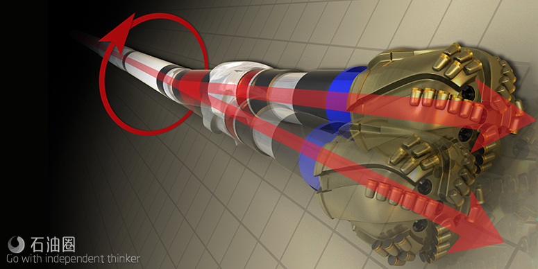
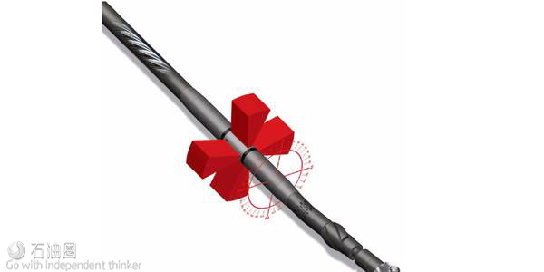
But to control well direction, most drillers today use geosteering methods that include a bottomhole assembly that incorporates rotary steerable systems to turn the well, and logging while drilling (LWD) formation evaluation tools to characterise the formation being drilled.
Directional drillers typically rely on resistivity measurements to determine the location of the upper and lower boundaries of the formation.
Better tools
Recent advances in resistivity tools have greatly enhanced the effectiveness of this method.
“The first ones came out about 15 years ago,” says Armstrong. “They used resistivity contrasts to determine the distance to a boundary and the driller steered the well based on that. The new formation evaluation tools have the ability to measure resistivity ahead of the bit.”
To drill a well path that can be readily cased and completed, drillers must first begin to turn the well to the horizontal at the appropriate depth and enter the formation at the right wellbore angle.
To gain that information, operators turn to offset well and seismic data that are often insufficient or highly uncertain.
One solution to this lack of information is to drill pilot wells into the formation. However, the high cost of deep-water rigs and the likelihood that these wells will not be completed make pilot wells an expensive data gathering strategy.
Operators have also used conventional LWD resistivity measurements to guide their entrance into the formation and to steer the wellbore.
However, most overburdens above target formations are conductive, and traditional resistivity tools are effective only in non-conductive formations.
Lack of depth control may be especially costly in terms of optimal lateral wellbore placement.
Before entering the target sands to drill an 8 ?-inch production hole, operators typically set a 12 ?-inch casing string. If the formation is shallower than expected, the driller may have to turn the well at a high angle after drilling out of the casing shoe to turn the well into the formation.
This could result in a high dogleg severity that could limit completion options.
An unexpectedly shallow formation may cause the driller to exit the base of the formation. To re-enter the formation, the driller would then have to make a directional change that would result in an upward wellbore angle and create a sump at the low point of the well.
Challenges for drillers
If the formation is deeper than predicted, the driller may turn the well too soon and drill horizontally above the formation or place the well in the suboptimal upper sections of the zone.
Consequently, the challenge to drillers is to determine the optimal depth for the 12 ?-inch casing shoe.
In some cases, operators can use offset log data to correlate to markers in the overburden to determine within an acceptable margin the bit’s distance from the producing sands. But in many instances, the overburden does not exhibit reliable markers.
Operators may determine bottomhole location using gamma ray (GR) tools to identify known geological markers in the target formation that have GR signatures.
However, traditionally GR sensors were located about 45 feet behind the bit, which meant drilling well into the formation to get a log.
“Traditionally, you have 30 feet, which is the length of the rotary steerable tool and another 15 feet to get to the gamma ray sensor and then another 15 feet so you can get 15 feet of log,” says Armstrong.
“So you have the bit 60 feet into the formation, and if you do need to steer to correct you have to make more correction than you would like, or it may even be too late.”
This drawback has been addressed in recent years by GR sensors located on the BHA close to the bit. However, the technique still requires the driller to enter the formation before picking a casing seat and, more importantly, relies on the existence of a geological marker that has a GR signature.
In response to this limitation, LWD service providers have unveiled resistivity LWD tools able to measure resistivity farther from the wellbore.
Introduced in 2005, the first of these deep directional resistivity LWD tools had a depth of investigation up to five metres and have been upgraded in subsequent years to depth of investigation of more than 30 metres away from the wellbore.
With that capability, drillers can pro-actively steer wells through long formations, which helps them avoid tortuous well paths that may result from the need to suddenly correct wellbore inclination or azimuth to remain in formation.
Uncertainties
Still, because drilling extended laterals in deep water is often made difficult by uncertain seismic data, complex geology, and low-resistivity formations that limit depth of investigation of deep-reading resistivity tools, directional drillers may not be able to determine reservoir top depth or the dip angle of the reservoir.
As a consequence, drillers have difficulty determining the optimal wellbore inclination for encountering the formation and determining the upper and lower reservoir boundaries that enable them to keep well within the formation during the ERD operation.
To address these unknowns, Sperry Drilling Services created a 3D Geosteering Sevice that integrates digital 3D geological earth models, directional well plans, petrophysical models and real-time LWD sensor data into an interactive geosteering application.
The LWD data combined with the company’s StrataSteer 3D software predicts and models the top of the entry point in the reservoir.
“The uncertainty in seismic and lack of log correlation between offset wells cause uncertainty in geological scenarios,” says Shaikh Aamir, senior technical adviser for Halliburton’s Sperry Drilling.
“However, real-time images for dip picking, structural analysis, filtering existing information with new real-time data and correlating it with selective offset wells leads to a better understanding of the geological scenarios, thus allowing accurate positioning to be obtained.”


 石油圈
石油圈

