CASEDHOLE WIRELINE LOGGING
Well integrity. In contrast to conventional, acoustic-based cement-evaluation methods, Halliburton has proposed a gamma-gamma technique that employs a tool with a Ce-137 source and a sodium iodide scintillation detector that is designed to be sensitive only to the cement in the annular space behind the inner casing. The detector response varies with different degrees of cement integrity. The count-rate ratio, and the dipping point values from the gamma-ray spectrum, are used to determine the amount of void space and its position inside the cement, which can be used to image channels inside the cement.
Heavy mud and thick casing. Two service companies recently described advances in ultrasonic logging systems that now allow cement and casing evaluation in wells with heavy mud and/or thick casing. New, specially designed transducers are central to both.
Schlumberger has field-tested a new high-powered/sensitivity transducer that employs both the pulse-echo and flexural-attenuation techniques. Using a transducer optimized for thick casing, the operating limit of the pulse-echo measurement was pushed beyond a 1-in. thickness; using a high-sensitivity thin-casing transducer, cement and corrosion evaluation is now possible in muds exceeding 16.7 lbm/gal. The new transducers are rated for temperatures up to 350℉ and pressures of 20,000 psi. The tool and associated processing software provide images of casing condition (shape, thickness and corrosion state), cement acoustic impedance and cement-induced flexural attenuation in a single run. In many instances, the cement-to-formation or cement-to-outer casing can be imaged as well, enabling determination of the casing position in the borehole, the cement sheath geometry and the sound velocities of the annulus.
Halliburton has tested a new pulse-echo tool that can evaluate cement and casing thicknesses between ¾-in. and 1.2-in., in mud weights ranging from 7 to 18 lbm/gal in SOBM, and up to 16 lbm/gal in WBM. The tool, which uses a high-sensitivity, low-noise, low-frequency transducer, is available in low- and high-pressure versions: The low-pressure version (3 5/8-in.) is rated to 20,000 psi; the high-pressure tool (4.438 in.) is rated to 35,000 psi. Both can operate at 350℉.
Fiberglass casing. Improvements in the operating temperature and pressure range of fiberglass casing, together with reduced cost, make it a viable option in oil and gas, disposal, groundwater monitoring, CO2 sequestration, saltwater injection, and geothermal wells. Fiberglass is lighter and more corrosion-resistant than steel, and performs well in temperatures and pressures up to 300℉ and 4,000 psi.
However, standard methods for evaluating cement bond in steel casing do not work in fiberglass casing due to its low acoustic properties, which are below the band limits of typical ultrasonic cement evaluation tools. Service companies are working on methods to enable ultrasonic cement evaluation in fiberglass casing. Schlumberger reported on preliminary research results.
Weatherford has tested evaluation of cement bond and casing thickness, using a high-frequency, ultrasonic scanner system. The scanner uses the ratio of amplitudes between the echoes reflected from the casing ID/OD to measure the cement acoustic impedance. The technique provides a quantitative measure of the cement impedance with the same accuracy and resolution as the measurement performed with steel API casings. The time difference between the echoes measures the casing thickness.
Since fiberglass casing is nonconductive, nonmagnetic resistivity and NMR logs can be used in EOR monitoring as an alternative to conventional saturation logs. NMR logs are useful in situations where EOR chemistry makes interpretation of these saturation logs difficult. Another advantage of NMR is the possibility of using a common physics of measurement at multiple scales. Schlumberger reported on a project in which laboratory coreflood and fiberglass-cased pilot and observation wells were monitored by NMR. The results indicated that NMR measurements, which are sensitive to fluid volume, can resolve remaining oil saturations to a precision of five saturation units in certain medium-viscosity oils, in porous formations.
Laser tubular inspection. Laser Techniques Co. has introduced a novel laser scanning technology for surface tubular inspection that may be adaptable for downhole wireline service. The system is called bore-erosion measurement and inspection (BEMIS)and is marketed by Laserstream through an exclusive arrangement. BEMIS employs a laser sensor that conveys information about steel erosion/corrosion, mechanical wear, eccentricity, and exact dimensions. The laser sensor rotates at high speed, typically generating more than 2,500 data points per revolution. These data are used to generate a high-resolution, 3D map of the tubular inner 0.010 surface. Linear resolution can be as fine as .010-in. or as loose as 1-in., depending on the application. Typically, measurements are accurate to ±0.002-in.
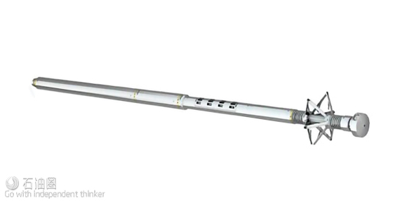
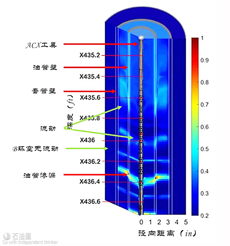
Leak detection. Halliburton introduced a system that uses a hydrophone array to locate and describe casing leaks and flow around the wellbore and behind casing (Acoustic Conformance Xaminer). The combined use of a receiver array and beamforming processing allows the array to triangulate on the sound/flow source and removes the high reliance on acoustic amplitude and frequency to accurately identify the leak point. Its results are superior to the unreliable, echo magnitude readings provided by previous generation tools.
High-definition data are stored downhole and can be downloaded at surface. The 1.69-in tool operates in continuous mode (25 ft/min.), to quickly identify areas with possible leaks, and in stationary mode to refine and confirm areas where leaks are identified. High-definition data stored downhole can be used in post-run data analysis that can provide flowrate and phase estimations at the locations with possible leaks, as well as 2D flow maps from which leak depth and radial location can be extracted. In controlled testing, flowrates as low as 0.01 gal/min. have been identified. The tool is rated to 350℉ and 15,000 psi. Minimum tubular inner diameter is 2 in.
Reservoir monitoring. Borehole gravity meters are very sensitive to changes in the earth’s gravitational acceleration. In boreholes, they measure changes in fluid/rock density and can monitor fluid movement in reservoirs. However, the high cost and large size of these devices has previously restricted their use in E&P, and limited their application to vertical wells. But given recent development of smaller, low-cost MEMS-based, and vector gravimeters that can be run in deviated and horizontal wells, time-lapse (4D) gravimetric surveys may become a routine alternative to monitoring reservoir floods in the near future.
EM visible proppants. Knowing the precise location of hydraulically placed proppants is critical for evaluating the success of stimulation and improving recovery on future frac jobs. Standard well-log-based methods using radioactive or new nonradioactive tracer proppant taggent are near-field techniques that detect proppant 18 in. to 24 in. from the borehole. Several university research groups are working on electromagnetic techniques that have potential for remote proppant detection and imaging. Central to these techniques is the use of electromagnetically visible proppant. These include electrically conductive coating, nanoparticles, or contrast agents that can be detected by surface arrays or downhole methods, such as crosswell imaging or a low-frequency induction logging tool.
Nanoparticle contrast agents. Two different groups of university researchers are investigating the use of nanoparticles to monitor production. The University of Utah is looking at nanoparticles (organic and inorganic) to enhance the electrical conductivity contrast between water and oil allowing it to be detectable by conventional induced polarization methods.58 The University of Texas at Austin group is studying the use surface-coated magnetic nanoparticles to change the magnetic permeability of the flood region; time-lapse crosswell tomography would be used to detect the low-frequency response (10 Hz) generated by a magnetic dipole source positioned in the injection well.71


 石油圈
石油圈