Pad B – Results and Improvements
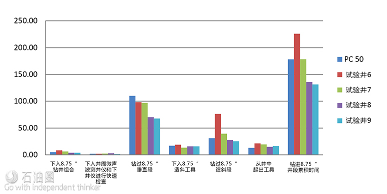
Pad B had four batch drilled wells. The drilling team planned to build on the previous pad’s drilling performance and attempt to drill each vertical interval in one run. The driller, however, needed assurances that the automation was capable of expanding the operating parameter window and unlocking further ROP improvement. The two major drilling limiters, the BHA dropping tendency and the cumulative damage to the bit, would need to be mitigated. This meant configuring a BHA to provide consistent tool face control and more neutral steering characteristics, which should also minimize the wellbore tortuosity, which was thought to be advantageous later in the well by reducing torque and drag. Fig. 11 shows the four wells and their cycle times for each of the measured operations:
● Well 6: Used a stabilized BHA with 15 drill collars, but the dropping tendency remained as in previous wells. The drillers also complained of a new problem: the tool face was difficult to control during sliding. The planned bit trip took about 22 hours with time spent pulling the string out of the hole to clear the salts and reaming into the hole starting around 7,360 ft. Consequently, the vertical interval took longer to drill than the average for the area. The stabilizer was removed for the second vertical run. The curve interval required three runs because of multiple trips and insufficient buildup rate (BUR). These issues were unrelated to the wired pipe and the DHAS, but the extra time brought the well total time to a disastrous 48 hours longer than the area average. This created grave problems for project economics.
● Well 7: Used a BHA similar to that used in Well 6, but with 12 drill collars in the first vertical BHA and a different shape on the string stabilizer to avoid problems in the salt. The planned bit trip was conducted successfully and set a record (by 1.5 hours) for all the operator’s wells drilled in the area. It was ahead of the previous three-well average by 31 hours. The dropping tendency was similar to the other wells and sliding still showed the same weight transfer issue; however, the ROP was much higher. Drilled the curve with the usual 2.38° bend and completed it in one run. The overall time for this well was 0.2 hours over the area average.
● Well 8: Used a slick, HWDP BHA with two dedicated bit runs to complete the fastest vertical to date for the project. This well had more sliding footage than previous wells, but at a higher ROP, resulting in a better overall cycle time. The curve was completed in one trip. The overall cycle time was 42 hours less than the field average.
● Well 9: Used a BHA similar to that used in Well 8 with a two-trip plan. Drilled the vertical even faster than the previous well. The curve was completed in one trip. Overall cycle time was 47 hours less than the field average.
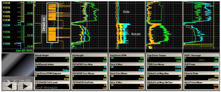
The downhole instrumentation captured multiple examples of weight transfer issues during sliding and rotating drilling by the end of Pad B as shown in Fig. 12.
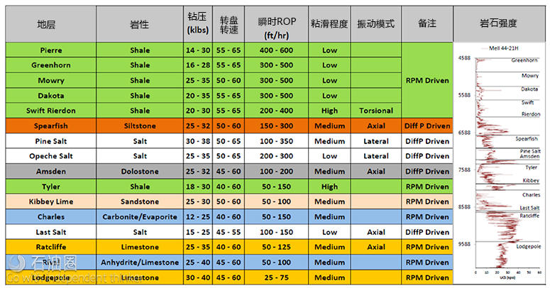
Fig. 13 shows the ‘driller’s roadmap,’ which was based on the operating parameters used on Pad A. The driller used the roadmap as a comparison point for operating parameters and the resulting ROP as each new well was drilled. Starting with Well 8 and continuing for the remainder of the project, the ‘reference curves’ for key drilling measures from the best offsets were displayed on the driller’s console to benchmark current performance.
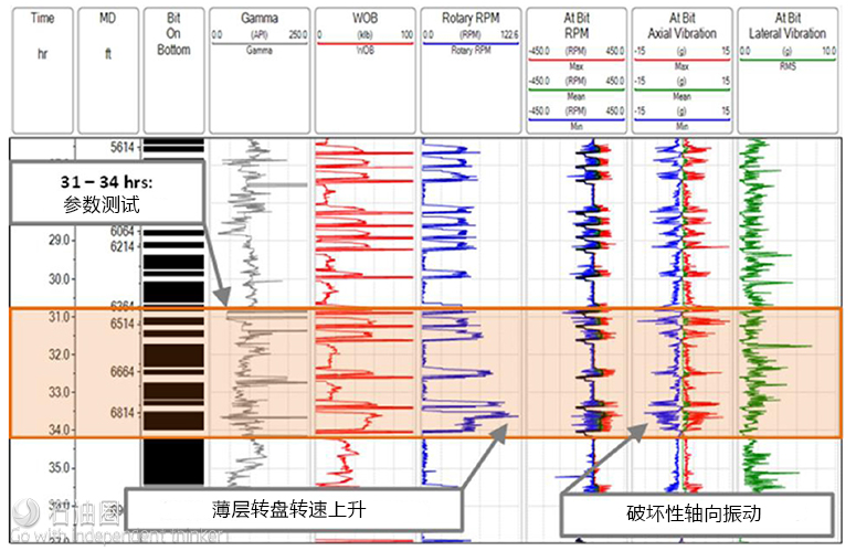
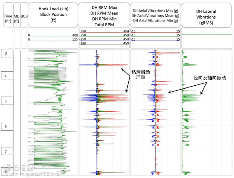
Damaging vibration at the bit resulted in a premature trip at 6,982 ft in Well 8 for penetration rate. A known stringer was encountered earlier than expected in the Rierdon formation during an aggressive parameter test in the tangent interval and was captured with the downhole telemetry as shown in Fig. 14.The formation transition was seen on multiple wells, but in this instance, high rotary speed and WOB were being used in a parameter mapping test. The result was vibration damage and a short run. Shortly thereafter, the protocol for conducting parameter tests was changed to avoid tests near known drilling hazards.
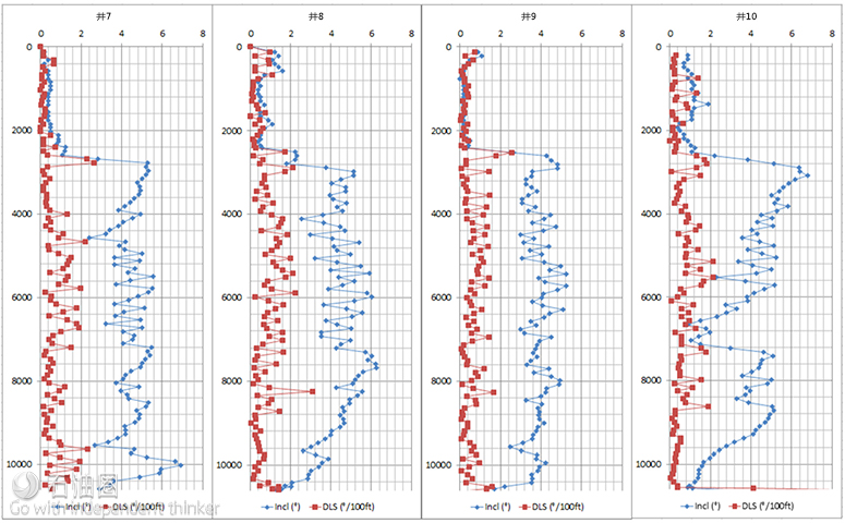
Fig. 15 illustrates the dropping tendency of the wells and the need for corrective sliding operations for the Pad B wells.
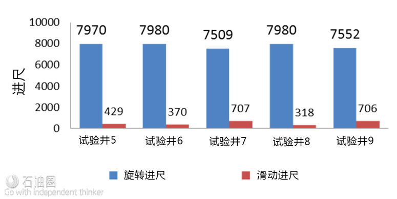
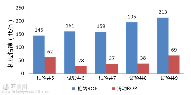
Fig. 16 shows Well 9 with the best average rotating ROP for the entire vertical, but Wells 7 and 8 have higher values than Well 5. Comparing the different sliding and rotating performance shows the difference in performance between the 7, 8, and 9 with over twice as much time spent sliding on 7. The overall interval ROP was determined by the sliding ROP in each well. Well 9 was the fastest. It also had the next-to-highest sliding footage, but the highest sliding ROP made up for it.
The results from the data analysis from the previous wells were completed and compiled into lessons. Data analysis showed that the standard practices for connections and on/off-bottom operations still differed significantly from event to event. Lessons included: Standardized connection practices, use of the driller’s roadmap, BHA stabilizer placement, communication practices, on/off-bottom practices, reaming practices, and tips on when to use the automatic drilling system.
The automation team now had two issues identified as value limiters. In the vertical interval, the key limiter was the dropping tendency in the upper portion of the interval which required sliding to correct. In the curve, the key limiter was the inconsistency in the BUR which sometimes led to multiple trips to deliver the curve according to plan. The different BHA configurations had introduced new problems with weight transfer during sliding in the vertical, but had not impacted the dropping tendency. The curve BHA had delivered different results over the course of the pad, and the rig team still preferred the current configuration with the 2.38° adjustable kickoff and 10 stands of 5 in. HWDP.
Pad C – Results and Improvements
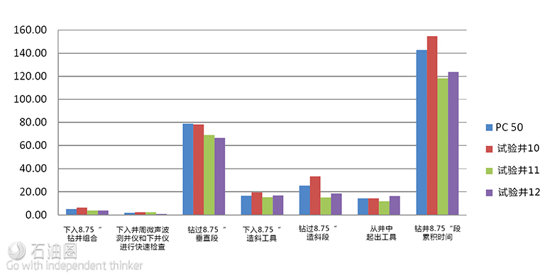
Pad C was a three-well pad located in an area to the east of Pad A and B. Unlike the consistent profiles of the earlier pads, Pad C presented a significant variety in the well profile tangent section. The team decided to use Pad C to test three-, six-, and nine-drill collar BHAs to find the optimum number of drill collars to limit downhole vibrations and reduce the dropping tendency from the BHA effectively. Fig. 17shows the three wells with their cycle times for each of the measured operations.
● Well 10: Drilled a 10° vertical tangent with six drill collars. Stabilized the collars with a watermelon stabilizer above the motor, but still had a dropping tendency. Pulled this assembly~100 ft short of KOP and used a curve assembly to complete the vertical interval. This assembly failed early in the curve, requiring a second run. Completed the overall interval 12 hours over the area average.
● Well 11: Drilled a 2° vertical tangent with two planned bit runs. Used nine drill collars and no string stabilization in the BHA. Reduced the curve assembly motor bend from 2.38° to 2.12° based on learnings from the previous well. Drilled the interval in one fast run. The overall time savings was 25 hours ahead of the average time.
● Well 12: Drilled a 4° vertical tangent with two planned bit runs. Used three drill collars and no string stabilization. The curve assembly configuration from the previous well completed the interval in one run. The overall time savings was 19 hours ahead of the area average.
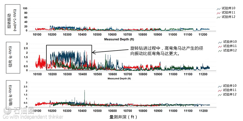
On Well 11, a fixed 2.38° bend curve assembly was used to finish drilling the last ~100 ft of the vertical section before kicking off and drilling the 8 ¾ in. curve section. A substantial amount of reaming was performed in the salt sections while tripping in hole with the curve BHA. Reaming with a high-bend angle motor caused high lateral vibrations, which damaged the bit and stressed the components of the motor. This resulted in an early trip for motor failure soon after reaching KOP in the curve section. The team learned the motor yielded plenty of BUR in the curve interval, but this came with reduced reaming capability with the 2.38° fixed bend. On Wells 12 and 13, a motor with a reduced bend angle of 2.12° proved capable of delivering needed BUR without penalty.
The lateral section of Well 12 was the first planned rollout of the 4 in. wired drill pipe. All drill string components normally used in the operator’s lateral strings (e.g., drill string vibration tool and string reamer tool) would have to be laid down because they were not wired components.
This would allow communication to the other pieces of the automation system below in the BHA. Not having these components in the BHA was a performance concern, but the focus was to proceed with the live string and drill as best as possible. The rig began tripping in the hole with the 4 in. wired string.
The crew found a communication issue and decided to trip back out of the hole. The problem was not identified and upon tripping back into the hole with the wired drillstring, the attenuation problems continued to occur. The decision was made to drill ahead in the lateral section. In the event of the network going dark or a network outage, the previously discussed plan was to drill ahead as usual with a non-wired drill pipe. This change in focus worked for the first 6,000 ft of the lateral section. The steering of the BHA became difficult because it was challenging to get weight to the drill bit.
The crew decided to trip out of the hole to pick up a new bit. Once back on bottom, the new drill bit had little effect on ROP or directional control. Multiple cycles of friction reducing beads were pumped down the well, which only provided temporary relief. The situation gradually worsened and the rig lost any time gained from the vertical and curve section. In spite of this, the overall well finished at a time savings of 42 hours ahead of the field average.
This was better than Well 10, but 6 hours slower than Well 11. The lesson learned was that it is hard to effectively drill the lateral section without the aid of the drill string vibration tool and string reamer tool. Further investigations were conducted to gain an understanding into the loss of communication with the4 in. wired drillstring. The root causes of the problem were identified and addressed by the provider, but could not be completed in time for the 4 in. string to be tested again on this project.
Pad D – Results and Improvements


 石油圈
石油圈