Development and Field Test of ESP Reliable Power Delivery System
Abstract
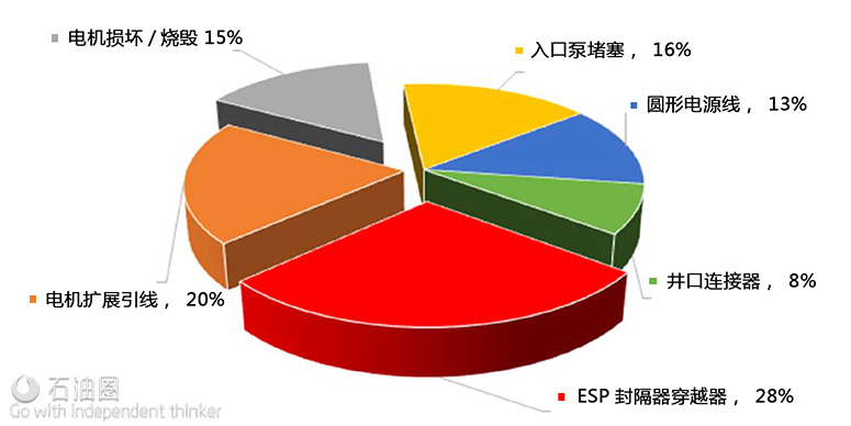
In high H2S and high pressure/temperature fields, the average run life of ESPs is still limited to 3 years. Dismantle Inspection Failure Analysis (DIFA) results show that around 50% of ESP failures are directly or indirectly related to electrical delivery problems concentrated in about 200ft between the packer and the motor. This paper presents a collaborative R&D effort to develop and trial test a Reliable Power Delivery System (RPDS) with the goal of extending the average ESP run life from the current 3 years to10 years.
Introduction
Reliability of electrical connections in Electric Submersible Pump (ESP) subsurface equipment is a Subject of high importance (Al-Sadah2014). Records show that, for instance, around 50% of electrical Failures in one key offshore field are related to the electrical connection below the ESP packer includes The Motor Lead Extension (MLE), as indicated in Figure 1.Moreover, severe service environments for ESP systems are generally defined as those applications where the wells have downhole H2S concentrations above 5% and CO2 concentrations of more than 5%. In such applications corrosion will affect the Run life of the equipment .The rate and extension of corrosion, however , can differ based on fluid partial Pressures, bottom hole temperature , and well history ( based on evidence of previous premature corrosion).
In order to alleviate this issue, a joint research project was initiated to develop Reliable Power Delivery System (RPDS) as a solution to prolong ESP run-life in a harsh environment.
System Description
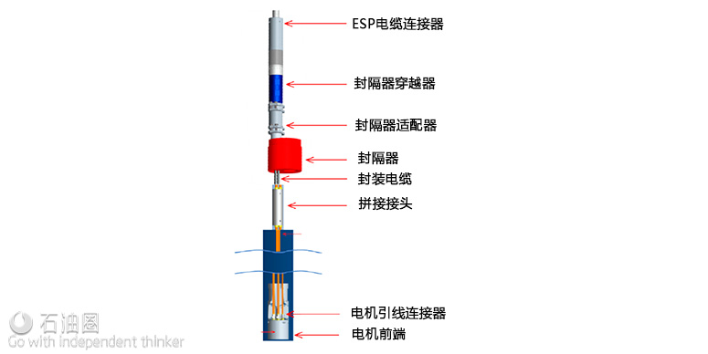
The RPDS configuration provides increased reliability over the conventional MLE configuration .The key and unique aspect of the RPDS system is the fact that all primary interfaces are field test able metal to metal, vastly reducing the potential failure modes caused by high H2S and rapid gas decompression. Scope of development includes modification of motor head to accept new feed through connectors, metal encased cable, splice connector below packer, packer adapter and penetrator and modification of ESP cable connector.
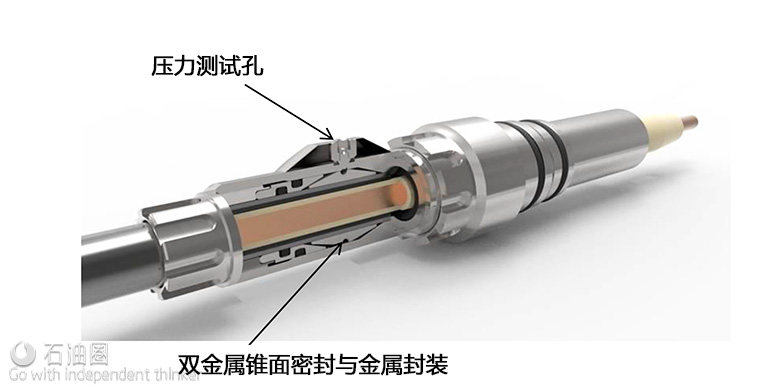
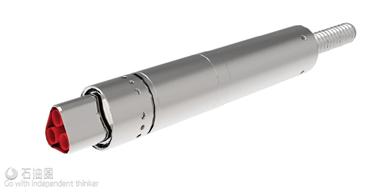
The new connectors are based on field proven subsea technology modified to suit power rating and architectural constraints. The motor head is configured with 3 single phase connections with primary metal to metal sealing to both the motor head interface and the metal encased MLE. The termination to the motor was modified with a special insulator and motor winding crimp arrangement to accept the individual feedthroughs. The motor head in corporates test ports in order to verify proper engagement of metal to metal seal during field installation by means of a simple pressure test tool.
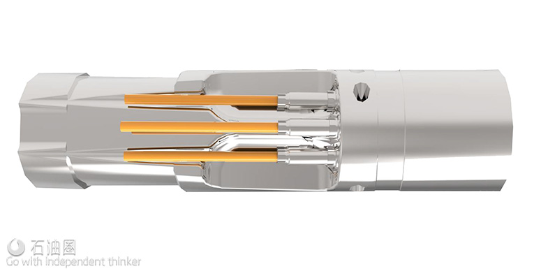
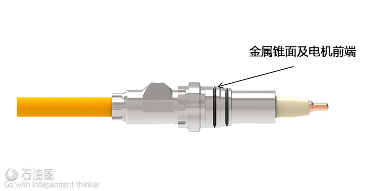
The electrical feedthrough connectors are constructed in such a way to include an Electron Beam Welded (EBW) insulating contact pin assembly which eliminates the need for primary elastomeric seals to the main housing. The contact pin is manufactured as an integrally moulded polyether ether ketone (PEEK) assembly which incorporates a metallic collar, which optimizes electrical field and minimizes stress. This collar also facilitates the final EBW process. The connector body includes a metallic differential cone seal to seal into the motor head machining profile. O-seals are incorporated to the sealing interface to facilitate a pressure test during installation.
On the back side of the feedthrough, a metal to metal seal is established with the encapsulated cable by using a combination of a dual conic swage ferrule and a compression olive. A retaining ring is torqued to apply compression to the ferrule thus setting the swage using a pre specified torque value. ThecompressionolivehasinternalandexternalO-sealsallowingthemetaltometalsealtobetested.
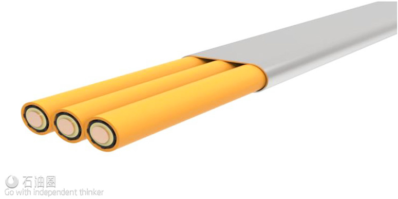
The new MLE has a configuration with each of the three phases is metal encased and connected individually to the motor head. Power is transmitted via AWG#4 solid conductors, insulated with PEEK material and protected with a unique fluoropolymer spline jacket. Traditional jacket lead has been replaced with an INCONEL® tube (625 or 825 alloy shown as Orange) in order to make the cable immune to rapid decompression effects and highly resistant to corrosion effects due to H2S attack.
In figure 6, every single insulated conductor is metal encapsulated and the conductors are maintained together in order to facilitate handling and installation in the field with low profile Monel armor.
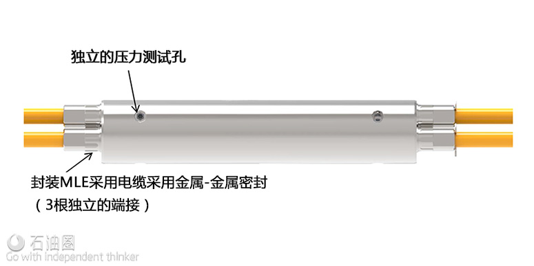
In order to facilitate assembly of the system in the field, a “splice” connection is added below the packer, being the only element to be terminated in the field. The splice connect or incorporates the same feature sand technology with respect to metal to metal primary sealing to the cable , identical to the motor feedthroughs. No potting or epoxy filling is required; metal to metal sealing is established between the connector and the metal encapsulated cable at both end sand is pressure test able during assembly.
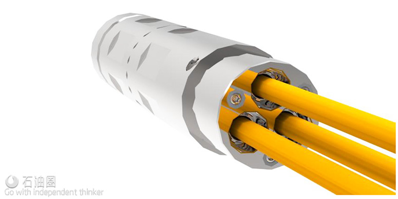
The packer penetrator has been designed to mate with different packer vendors. It includes an offset adaptor assembly to avoid interference with first pup joint / tubing installed above the packer. The bottom side of the penetrator connects with the metal encapsulated conductors and is preassembled in the shop and it is possible to be shipped to field with the packer and splice connector already terminated, connected and tested. It incorporates same key features and sealing philosophy as the motor feedthroughs.
The upper section of the penetrator mates with the ESP power cable. Despite this side of the connector will be submerged in completion fluid and won’t see well fluids, it incorporates as well a metal to metal seal at the connector interface to the packer penetrator.
The ESP power cable connector is based on subsea dry mate technology. It interfaces with the packer penetrator and allows the ESP cable to be connected to it. It has been modified to suit AWG#2 main cable with a new cable seal and termination sleeve. Some specific installation tools have been developed and a detailed installation and handling procedure for termination and testing both at the operational base and at the field have been produced.
Component Level Testing–Metal Encased MLE
Encapsulated Cable Cold Bending Test
This test is to simulate the finished motor lead bending over the sheave during installation at the well site. In some parts of the world installation temperatures can be as low as -40°F (-40°C) therefore test samples were bent after being stored at -40°F (-40°C) for a minimum of 24hrs. This test was performed 5 times around a 16” mandrel which is over half of the 42” sheave diameter. This small reel was able to fit inside a freezer. Even though this MLE was tested using a 16” mandrel, the minimum bending diameter recommended forth is product is still 42”.Results show no damage or loss of electrical properties because of the cold bending and therefore this test is considered as a pass.
Encapsulated Accelerated High Temperature Aging Test
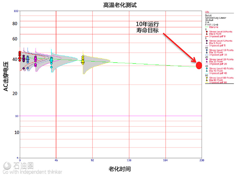
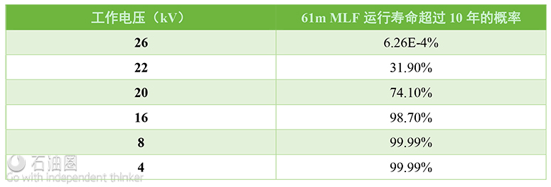
This test is set up to simulate material aging which will occur during the products 10 year expected life at a maximum temperature of 350°F (176°C) . Forth is test we chose to accelerate the aging by testing the samples at 420°F(216°C) for 5 days ,10days, 20days, 40days, and 80 days. The Arrhenius model (Spahi and Parsley 2013) indicates that for every 10° C increase in temperature the product life is reduced by half. Therefore, if the expected life is 10 years at 176° C the expected life is reduced to 0.625 years (228 days) at 216°C. By doubling the aging duration between each data set we can plot the results on a logarithmic scale which best fits the expected degradation curve, Figure 10. This degradation curve will then be extrapolated to 10 years and a run life probability established based on the operating voltage. The result is the percent probability that the unit would operate for 10 years at various operating voltages. As shown in the table below, at operating voltages equal to or less than 8kV there is a 99.99% probability of exceeding 10 years in run life.


 石油圈
石油圈
