Well control trends and mitigation tools: A technology update
Improving oil prices have brought increased drilling and production, but also well control failures, due to reduced quality assurance and shortages of competent personnel. Embedding lessons learned from these events, along with integrated use of technology and specialized expertise, can mitigate well control risks.
This article profiles four well control risk trends and mitigations that have the potential to minimize risk for operators worldwide, and change the analysis and management of those risks.
MULTI-WELL PAD DESIGN RISKS
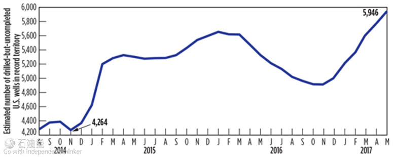
The oil price downturn pushed operators to adopt a focused, multi-well pad design that allows for maximized drilling efficiency with minimal drilling and mobilization costs. This can be observed in the surge of drilled-but-uncompleted (DUCs) wells in the Lower 48, after OPEC’s initial production reduction in third-quarter 2016, Fig. 1. However, as these wells are brought into production, an increase in focus and expenditure on well control is needed to address the risks related to stimulation, production and other SIMOP activities. This means that the inherited operational efficiencies during the downturn will have to be adapted to address the change of drilling objectives. One area that needs additional risk mitigation involves design philosophy of the well pad, itself.
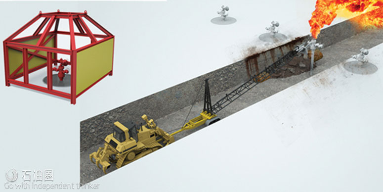
Due to construction costs and the need to reduce environmental impact, pad designs usually involve a compromise between minimized footprint and operational sizing requirements, while well control risks often receive insufficient consideration. The close spacing of wells on these pads can intensify the impact of a well control event on asset integrity, personnel safety, and business continuity. One key issue is to confine such impact to the problem well, without inducing collateral damage to the surrounding wells, such as shown by the confinement cage design in Fig. 2.
Another common issue is access and well spacing needed to conduct well control response activities, as illustrated in the same figure by the dimensions and space associated with an Athey Wagon operation. Other issues include placement of control barriers and establishment of proper SIMOP procedures, as well as hazards associated with well effluent and well control fluids during an event. Such issues can be identified and addressed with adequate, upfront planning and site-specific assessment during the design phase of the well pads. It is important to involve the services of well control professionals to provide the critical experience and technology needed to develop a proper design.
WELL CONSTRUCTION RISKS
Much of the target formations in unconventional shale plays are tight or have low permeability. Typically, formation fluid cannot flow without large-scale artificial stimulation, such as hydraulic fracturing. As a result, and in the current low-cost environment, well control risks may not always receive the proper attention in planning and operating wells. Compromises in design often involve reducing the depth and/or number of casing strings. This can reduce the capacity of a well significantly to deal with a kick from a permeable zone that is unexpected or has not been cased-off. In some cases, flow from such a zone is masked by losses to another zone, and the kick is not detected until it is too late, often due to the assumption that “these wells don’t flow.”
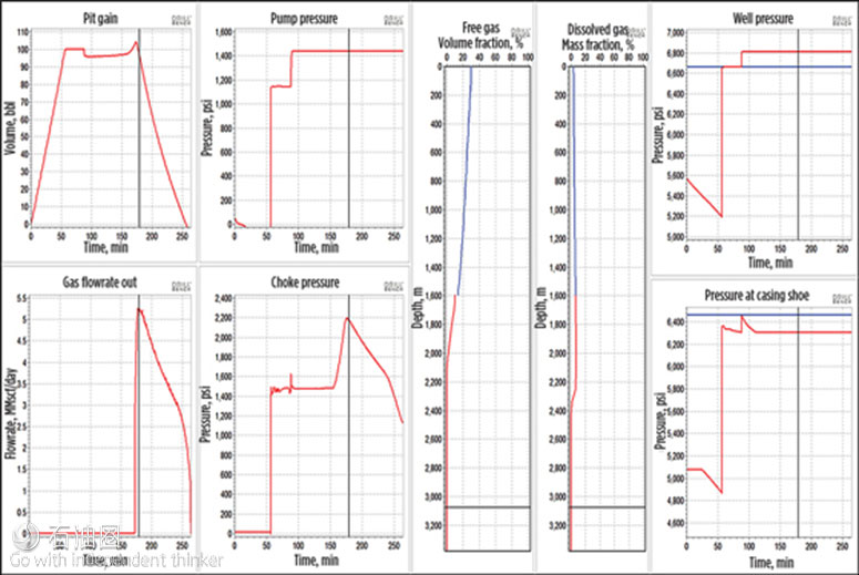
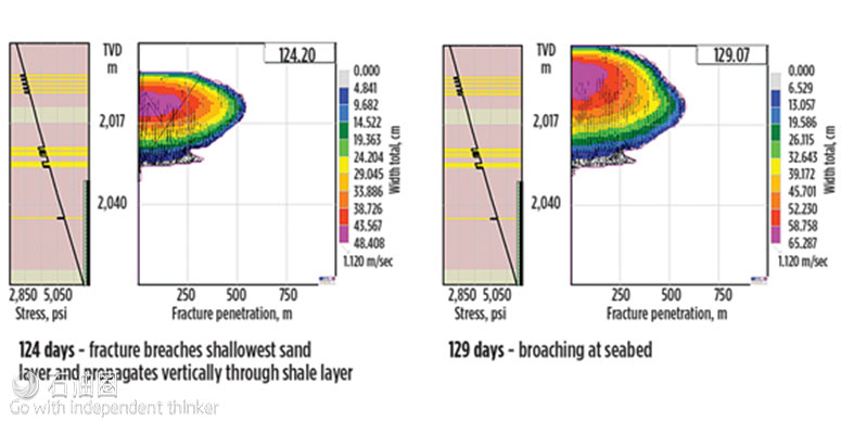
To meet these challenges with a sustainable solution, a well control-risk management program is needed to identify, analyze and mitigate these issues. Such a program also can establish guidelines that should be adopted as long-term implementation for other similar wells, formations or pads. For example, multi-phase kick modeling (Fig. 3) can be used to evaluate adequacy of depths and number of casing strings for kick handling. In cases where cross-flow can be an issue, or when a kick broaches a casing seat that may result in a surface blowout, additional simulations, such as those shown in Fig. 4, can be used to evaluate these risks and develop the needed mitigation. These tools help assess the suitability of a well design and the equipment needed to maintain proper primary well control, without under- or over-estimating the risks and costs involved.
WELL PLACEMENT RISKS
The recent increase in use of high-density spacing, multi-well pads, often containing up to 40 shale oil wells each, has increased the risk of well placement problems significantly. Close well spacing of long horizontal sections requires accurate placement of the entire wellbore, all the way from heel to toe. This allows little or no opportunity to make mid-course adjustments, as can be done for conventional wells with discreet targets. The risks include problems ranging from missing the reservoir target to an inadvertent collision with a production well, and usually can be attributed to the management of well placement uncertainties during drilling.
There have been a number of cases, where an operator’s drilling of a well inadvertently intersects a flowing production well drilled from the same pad or a nearby pad. Other cases involve inadvertently fracing into a drilling well, or drilling into the factures of a well that is producing with stimulated pressure. In both scenarios, the open-hole section of a well actively drilling is typically not designed to handle the full stimulation or flowing pressure of production. This usually results in a well kick that can break down the casing shoe, leading to an underground blowout or broaching to the surface. These risks can be reduced significantly by applying current well placement technologies, to design and maintain proper control of wellbore geometry.
These placement risks are significantly more complicated when the need arises for drilling a relief well. This typically occurs when surface access is not available to cap or re-enter a blown out well, due to excessive damage or obstruction by debris on the surface. In this scenario, placement uncertainty associated with any of the target or adjacent wells introduces critical complications that add significant time, and cost, to the relief well operation. Such placement uncertainty can be addressed readily during the planning and execution phases of well construction, at a cost far less than any resulting complications, should a relief well be needed.
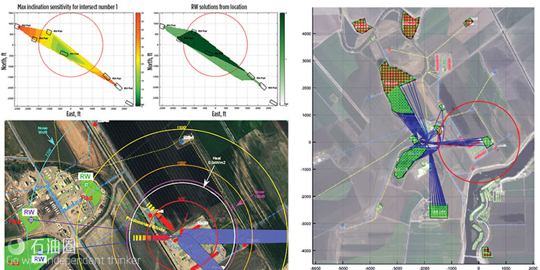
The same technology can be applied in designing both the placement geometry of a relief well and an optimum surface location to drill it from. For horizontal wells, the most effective intersection point for a relief well is at the heel of the wellbore. Figure 5 shows results from a relief well planning surface location study for a congested, multi-well and multi-pad field. It provides the design that allows a relief well to reach the heel and kill any of the wells in the field, if needed.
HYDRAULIC FRACTURING RISKS
The use of large-scale hydraulic fracturing for shale oil has brought some new considerations to casing design for these wells. Conventional factors, such as maximum allowable surface pressure, are usually included in the designs used by most operators. One aspect that may not always be addressed adequately is the complicated thermal, pressure and tension cycling, and its impact on the casing. Such cycles occur during drilling, cementing, fracing, flowback and production of the well. There has been quite a few cases of casing failure during flowback, production or other operations, resulting in pressure communications behind casing, or broaching, or blowout, or progressive escalation through all of the above. Post-analysis in most cases indicates parting of couplings, due to excessive tension, rather than pressure burst of the casing itself.
Technology is now available to provide the engineering analyses and simulations to evaluate these complex loading cycles and establish the proper casing design. This is primarily carried out using the latest technology in Computational Fluid Dynamic (CFD) and Finite Element Analysis (FEA) models, which are well-suited to perform such analyses for the entire lifecycle of the well, as needed.
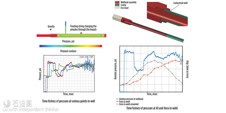
In a post-incident analysis, such CFD and FEA models were integrated to investigate the reasons for an ejected wellhead and frac stack during a fracing operation. The analysis included complex variations of temperature, pressure and tension loads experienced by the production casing. It was concluded that the failure mechanism was tension recoil, not annulus overpressure. The results led to an improved design for subsequent wells with appropriate weight, grade and metallurgy for the treatment string, as well as improved safety practices during fracing operations. Some of the modeling graphics from this case study are shown in Fig. 6.
CONCLUSIONS
The recovery in oil prices has created an increase in drilling and production activities, along with which has come an increase in well control failures. Most of these are either due to mechanical issues related to reduced quality assurance and control of operations, or due to shortages in competent personnel and proper equipment. Wild Well is working to embed the lessons learned from those events during design, execution, and end-of-life well cycle. The integrated use of technological tools and specialized expertise can mitigate significant well control risks and, thus, reduce overall operating costs.

 石油圈
石油圈