Liner extends mean time between failures
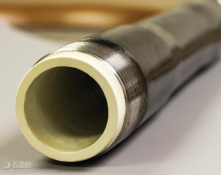
Lightning Rod and Pipe is offering a lined tubing technology that reduces the meantime between failures in PCP and rod pumping applications. LightningFlo LF115 uses a unique polymer that lowers frictional wear from rod movement, resists corrosion-causing chemicals and can maintain integrity in high-temperature operations.
The tubing’s high-performance resin addresses the limitations of early offerings at a lower cost. The new resin works well in high temperatures, is more resistant to corrosion, has lower coefficients of friction, and stands up to abrasive wear.
LightningFlo LF115 lined tubing uses raised temperature polyolefin ketone (POK). It is now being extruded into thermoplastic tubing liners at a much lower price than other high-performance resins. POK was originally commercialized by Shell Chemical as a replacement for HDPE in offshore applications, where higher performance was needed. POK polymers have few known solvents and are particularly resistant to salt solutions, hydrocarbons and most other chemicals present in oilfield applications.
Thermoplastic liners tend to collapse when pressure is reduced abruptly inside the liner in the presence of an annular pressure. This can occur in oil wells when the tubing is pressured up and bled off rapidly. The tendency to collapse is much greater, if the permeability of the liner is high. Laboratory testing shows that a 5-in. pipe lined with POK has twice the collapse strength at room temperature than a pipe with HDPE liner.
Additionally, successful laboratory tests have validated the specifications of the liners. Multi-component crude exposure testing was done over an eight-month time period over a temperature range from 68°F to 176°F. The modulus, yield stress and elongation properties were relatively unchanged after this test. A separate eight-month test exposed POK to a fluid from a North Sea sour gas environment at 221°F. Tensile properties stabilized after two days of exposure and remained relatively unchanged for the remainder of the testing period. The POK liners have been proven to extend the mean time between failures in well installations in multiple locations over the last year.
PLUNGER LIFT DEVELOPMENTS
Plunger lift is used commonly to remove liquids from gas wells or produce relatively low volumes in high-GOR oil wells. Because the plunger provides a “seal” between the liquid and the gas, a well’s energy can be used to lift liquids out of the wellbore efficiently.
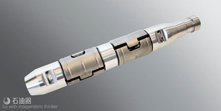
Pad sleeve bypass plunger. A pad sleeve bypass plunger, by PCS Ferguson (part of the Dover Artificial Lift group) reduces shut-in times and maximizes production. This plunger is the first of its type on the market, making more trips with faster fall times. It often helps wells achieve a significant increase in daily production. This padded version has more controlled travel times than the traditional sleeve and allows for a tighter seal in wells with tubing irregularities.
The ball and sleeve are held in the lubricator by the separator rod and latch. When the latch opens, the combination of the differential pressure and the rod hold the sleeve, while the ball falls toward the bottom of the well. When the differential pressure decreases, the sleeve begins to follow.
When the sleeve reaches the bottomhole bumper spring, it joins the ball and forms a seal. Pressure builds, causing the ball and sleeve to travel together while lifting fluid to the surface. When the plunger reaches the lubricator, the separator rod extends through the sleeve, knocking the ball down the tubing and the cycle repeats.
A well in Bridgeport, Texas, was producing 5 bopd and 500 Mcfgd, using a traditional 9-in. sleeve and a stainless steel ball. The well is 6,760 ft deep and has slight tubing irregularities.
The traditional sleeve plunger was replaced with a pad sleeve bypass plunger. After three months, the new plunger traveled 4,735 round trips, running at 11.5 min/trip. The plunger increased oil production 40% and gas production 10%.
GAS LIFT DEVELOPMENTS
Gas lift involves injecting gas through a well’s tubing-casing annulus. Injected gas aerates the fluid to reduce its density; the formation pressure is then able to lift the fluid column and force it up the wellbore. Depending on the nature of the well’s production and the characteristics of the lifting equipment, gas may be injected continuously or intermittently.
Improved gas lift for liquids-rich wells
Gas-lift is gaining popularity in oil shale wells. However, the design of gas-lift compressors is virtually the same as that used for gas sales, even though the two processes have different requirements.
This standard design is physically capable of performing either task, but the overriding focus of the present design is to prevent gas from overheating. With gas-lift, the focus should, instead, be on preventing the gas from being too cold. The focus on preventing high temperatures resulted from downstream equipment that functioned poorly above 100°F, and often gas sales contractual temperature limitations are 130°F or lower.
Design components favorable to “gas sales” work against the successful operation of a gas-lift compressor, because NGLs have not been removed, due to the lack of an on-site gas plant. When these liquids go through the compression cycle, they often condense in the gas coolers. This causes problems in the compression process, and results in additional expense, potential downtime and environmentally unfriendly practices.
Two prevalent operating problems caused by hydrocarbon condensation in a gas cooler are freezing dump lines, and hydrate formation plugging of components. In a frozen dump line, components such as propane, are in a liquid phase at 150 psig and typical first inter-stage pressure ranges. When dumped to a tank operating at atmospheric pressure, the propane will vaporize, extracting the heat of vaporization from the surrounding environment.
Propane has long been used as a refrigerant because of the significant cooling that is achieved when this happens. A secondary issue is the vapor cloud being introduced into the tank, and whether tank vapor recovery is designed to handle this. The end result can be a significant recycle (or recirculation) of propane, greatly reducing the efficiency of the gas-lift compression system.
Continuous methanol injection is used to combat the problems of hydrate formation and dump line freezing. However, the practice of pumping methanol, besides being expensive, is also somewhat dangerous, as methanol burns without a visible flame. As widespread use of methanol expands with the shale plays, this safety consideration should not be ignored.
According to Encline Lift, an alternate method for solving these two problems is to prevent them from occurring in the first place. This is done by designing the gas cooling system to keep temperatures in the vapor region (yellow) of the phase diagram, where hydrocarbon condensation will never occur. For gas-lifted wells with paraffin issues (exacerbated by lean gas injection), leaving the final outlet temperature above 150°F may suppress paraffin formation in the upper portion of the tubing string.

 石油圈
石油圈


