MPD and continuous circulation technology overcome deepwater challenges
MPD STRATEGY
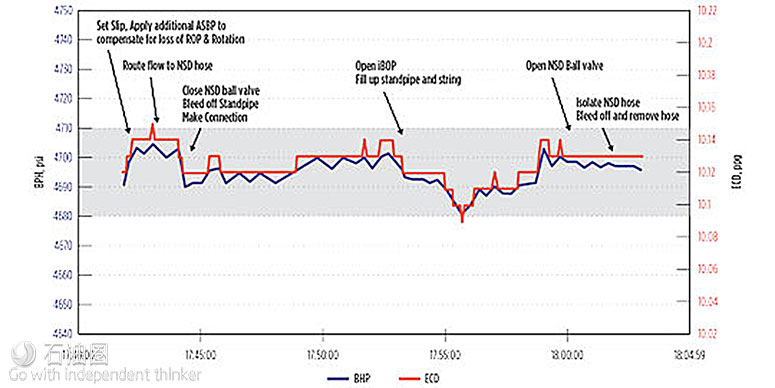
Stopping and starting the rig’s circulation system is a primary source of drilling NPT resulting in lost circulation, kicks, sloughing, stuck pipe, and differential sticking. A key drilling strategy was to use CCS to keep the pumps running at all times to provide a safe, simple, effective MPD solution. Figure 3 illustrates making a connection with the CCS system to maintain +/– 15 psi BHP control accuracy during drill pipe MPD connections. An additional 100 psi MPD ASBP was applied during the connection to compensate for the loss of drilling ROP and RPM.
CCS is the first step in MPD management of wellbore pressures and avoiding significant pressure variations during drill pipe connections. Using CCS with a MPD system allows a constant ECD profile to be maintained along the entire open hole section while drilling and making connections. Its use avoids the need to re-establish steady state circulating conditions required when using conventional drilling or standard, older type MPD techniques.
Once continuous circulation is established, MPD allows formation pressure and fracture pressure profiles to be determined. This supports active and continuous BHP control within the PP/FG window. MPD techniques were used to perform dynamic flow checks, dynamic FIT and LOT, squeezing lost circulation materials (LCM), kick and loss detection, dynamic well control, CBHP methods, and MPC.
Execution of the well control matrix is achieved using dynamic MPD well control to increase the BHP until MFI equals MFO to stop the influx and circulate it out of the wellbore without shutting in the well using the rig BOPs.
The pore pressure trend illustrates the degree of formation depletion or overpressure, which determines whether the current MPD drilling mud weight is statically overbalanced or underbalanced with respect to the highest pore pressure encountered.
The lower pressure boundary for the drilling window is constrained by pore pressure or the minimum pressure required for wellbore stability, whichever is higher (typically the latter in this case). The higher boundary is established by performing dynamic MPD FIT / LOTs or dynamic MPD flow checks when mud losses are encountered.
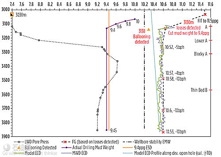
For example, drilling operations in one of the wells performed a MPD FIT to 11.5 ppg EMW, indicating the presence of a usable mud weight window, Fig 4. Due to high ECD with 10-ppg mud, weight was reduced 9.6 ppg. Drilling continued to the top of the A formation, where the LWD pore pressure tool was deployed to determine a formation pore pressure of 7.23 ppg.
For example, drilling operations in one of the wells performed a MPD FIT to 11.5 ppg EMW, indicating the presence of a usable mud weight window, Fig 4. Due to high ECD with 10-ppg mud, weight was reduced 9.6 ppg. Drilling continued to the top of the A formation, where the LWD pore pressure tool was deployed to determine a formation pore pressure of 7.23 ppg.
The mud weight was reduced to 9.4 ppg when mud losses were detected by the MPD system. Increased return flow was detected within 8 m of drilling, when ECD fell below 10.3 ppg when rig pumps were cycled for an MWD directional survey. After that point, ECD was maintained above 10.3 ppg EMW to prevent flow back from the formation. The formation pore pressure ramped up to 9.62 ppg as drilling continued into the formation. Minor mud losses were observed in the B formation if ECD exceeded 10.6 ppg EMW.
Managed pressure cementing
The 8.5-in. hole section on the same well was drilled using MPD with a statically underbalanced and dynamically MPD overbalanced EMW. Mud losses at the top of the A formation required a dynamic MPD flow check that indicated a 10.52 ppg fracture gradient. Formation flowback was detected when ECD dropped below 10.3 ppg during an MWD survey a few meters from the loss zone. The resulting drilling window was 0.2 ppg EMW or 88 psi between flow-back into the well bore and losing mud into the A formation. In addition, seepage losses were observed in the B formation when ECD exceeded 10.6 ppg EMW.
The narrow window required precise BHP pressure control in order to maintain constant bottom hole pressure in the depleted zone. The information gathered using MPD techniques was critical to prevent influxes and losses during cementing operations.
There were two key cementing objectives for this smart injector well: provide good zonal isolation of the depleted A formation and critical injection zones; and eliminate the cost of running an additional liner extension tie-back in the event cement could not be placed above the depleted A formation and top of liner hanger.
MPC discussions began during drilling operations when it became apparent that conventional cementing techniques would fail to meet the objectives. The result was the first deepwater MPC operation successfully executed globally. It presented significant challenges due to the narrow pressure margin, as this was a deepwater well with an 88 psi drilling window, with high fluid mobility.
A fast-track MPC initiative identified the key tasks required to cement the well using the MPD system. The first task was to simulate the planned cement job and develop an ASBP backpressure and pumping schedule. A MPD cementing procedure was written based on the cement program and recommendations from the MPD hydraulics simulation. A contingency plan was created and the MPD system was swiftly customized for safe, efficient MPC operations.
The procedure involved running the 7-in. liner very carefully to manage surge pressure, losses, and ballooning. Once the liner was set, the well was displaced to underbalanced fluid using the predefined pumping and MPD ASBP backpressure schedule to maintain constant BHP.
The liner was cemented while managing a pressure schedule with multiple fluid gradients in the well. Concurrently, the ASBP was reduced to transition the well from a dynamically MPD-underbalanced state, to a statically overbalanced state with cement in place. The liner packer was set and tested, and excess cement was circulated out of the hole.
MPD/CSS ADVANTAGE
MPD with CCS was used to drill a total of approximately 42,979 ft (13100 m). Up to 60 CCS subs were made up in the drillstring to perform back reaming in the deviated and horizontal hole sections. A total 939 CCS connections were made during the project campaign with a 99.5% success rate. The average drillstring connection time using CCS equipment was 10 min. and the total slip-to-slip average connection time was 18 min.
The operations achieved greater understanding of real-time wellbore and formation pressure, and applied that to avoid pressure-related drilling problems that previously compromised safety and efficiency, and in some cases precluded any drilling at all.

 石油圈
石油圈


